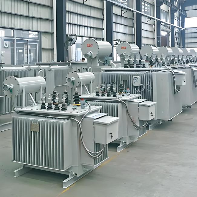
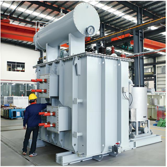
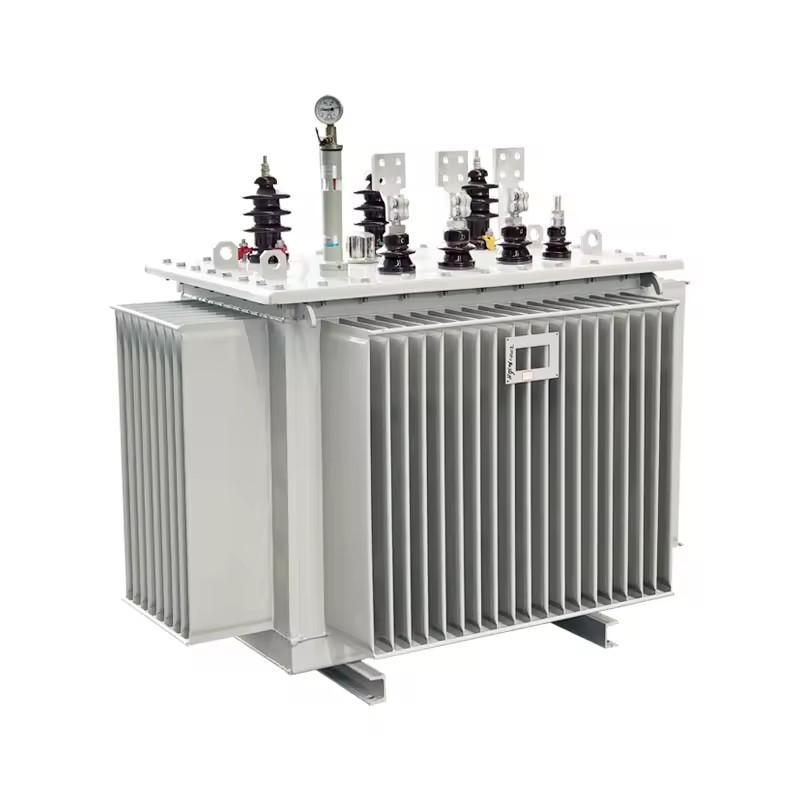
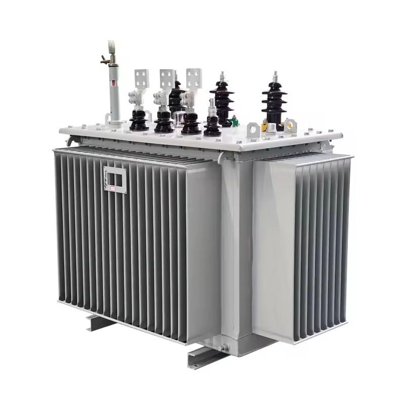
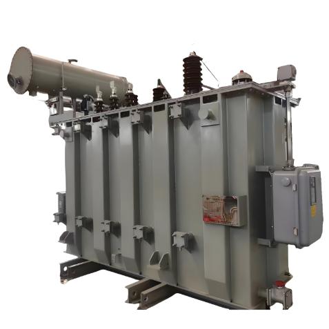
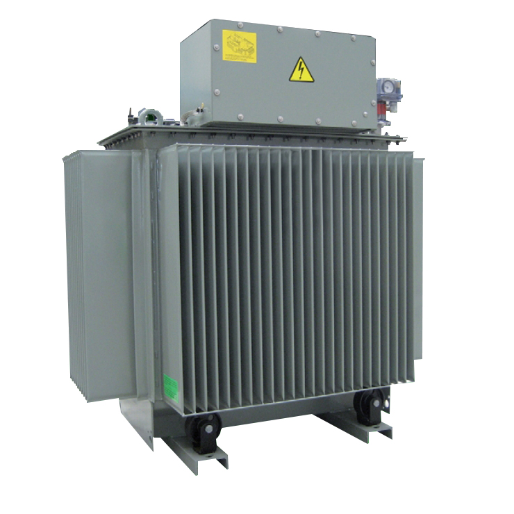
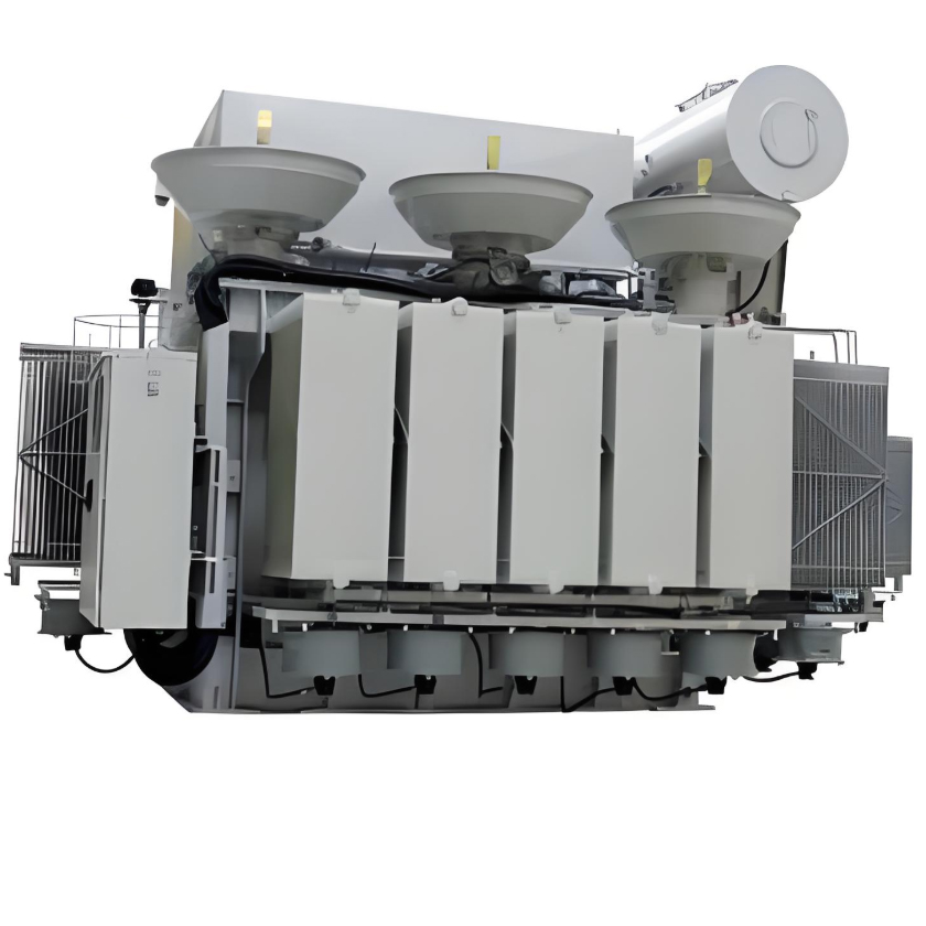
35kV On-Load / Off-Circuit Tap-Changing Oil-Immersed Power Transformer
Key attributes
| Brand | ROCKWILL |
| Model NO. | 35kV On-Load / Off-Circuit Tap-Changing Oil-Immersed Power Transformer |
| Rated voltage | 35kV |
| Rated frequency | 50/60Hz |
| Rated capacity | 3150kVA |
| Series | S |
Product descriptions from the supplier
Product Description
This product is a 35kV oil-immersed power transformer, available in both on-load and off-circuit tap-changing configurations. It is specifically designed to meet the stringent demands of modern power grids for voltage stability and power supply reliability. Utilizing advanced technology, it enables smooth voltage ratio adjustment either during energized operation or while de-energized, ensuring the output voltage consistently remains within the rated range. It is an indispensable core component in transmission and distribution systems.
Technical Parameters of S11 Series 50~1600kVA 35kV Power Transformer
Model Specification |
Voltage Combination and Tap Range |
Connection Group |
No-Load Loss (kW) |
Load Loss (kW) |
Short-Circuit Impedance (%) |
No-Load Current (%) |
Gauge (mm) |
Outline Dimensions (Length * Width * Height mm) |
Total Weight (kg) |
||
High Voltage (kV) |
Tap Range (%) |
Low Voltage (kV) |
|||||||||
S11-50/35 |
35 38.5 |
±5 ±2×2.5 |
0.4 |
Gyn11 Yyn0 |
168 |
1150 |
6.5 |
2.0 |
660 |
1160 * 810 * 1650 |
714 |
S11-100/35 |
232 |
1919 |
1.8 |
660 |
1300 * 1150 * 1745 |
1110 |
|||||
S11-125/35 |
272 |
2261 |
1.7 |
660 |
1900 * 980 * 1820 |
1310 |
|||||
S11-160/35 |
288 |
2689 |
1.6 |
660 |
1900 * 980 * 1930 |
1475 |
|||||
S11-200/35 |
344 |
3163 |
1.5 |
660 |
1870 * 990 * 2080 |
1707 |
|||||
S11-250/35 |
408 |
3762 |
1.4 |
660 |
1870 * 1100 * 2090 |
1805 |
|||||
S11-315/35 |
488 |
4532 |
1.4 |
820 |
2210 * 1060 * 2120 |
2360 |
|||||
S11-400/35 |
584 |
5472 |
1.3 |
820 |
2240 * 1080 * 2150 |
2442 |
|||||
S11-500/35 |
688 |
6584 |
1.2 |
820 |
2240 * 1080 * 2160 |
2787 |
|||||
S11-630/35 |
832 |
7866 |
1.1 |
820 |
2270 * 1090 * 2160 |
2868 |
|||||
S11-800/35 |
984 |
9405 |
1.0 |
820 |
2450 * 1110 * 240 |
3640 |
|||||
S11-1000/35 |
1152 |
11543 |
1.0 |
820 |
2480 * 1280 * 2300 |
3900 |
|||||
S11-1250/35 |
1408 |
13936 |
0.9 |
820 |
2480 * 1290 * 2330 |
4680 |
|||||
S11-1600/35 |
1696 |
16673 |
0.9 |
1070 |
2600 * 1460 * 2370 |
4835 |
|||||
Note: The above parameters are for reference only and can be customized according to customer requirements.
Technical Parameters of S11 Series 630~31500kVA 35kV Power Transformer
Model Specification |
Voltage Combination and Tap Range |
Connection Group |
No-Load Loss (kW) |
Load Loss (kW) |
Short-Circuit Impedance (%) |
No-Load Current (%) |
Gauge (mm) |
Outline Dimensions (Length * Width * Height mm) |
Total Weight (kg) |
||
High Voltage (kV) |
Tap Range (%) |
Low Voltage (kV) |
|||||||||
S11-630/35 |
35 38.5 |
±5 |
3.15 6.3 10.5 |
Yd11 |
0.832 |
7.866 |
6.5 |
1.1 |
820 |
2390 * 1000 * 2200 |
4095 |
S11-800/35 |
0.984 |
9.405 |
1.0 |
820 |
2420 * 1150 * 2250 |
4550 |
|||||
S11-1000/35 |
1.152 |
11.15 |
1.0 |
820 |
2450 * 1300 * 2300 |
4880 |
|||||
S11-1250/35 |
1.408 |
13.94 |
0.9 |
820 |
2480 * 1350 * 2360 |
5100 |
|||||
S11-1600/35 |
1.696 |
16.67 |
0.8 |
1070 |
2550 * 1490 * 2400 |
5280 |
|||||
S11-2000/35 |
2.176 |
18.38 |
0.7 |
1070 |
2632 * 1884 * 2537 |
5380 |
|||||
S11-2500/35 |
2.56 |
19.67 |
0.6 |
1070 |
2691 * 2276 * 2597 |
6160 |
|||||
S11-3150/35 |
3.04 |
23.09 |
7.0 |
0.56 |
1070 |
2842 * 2430 * 2617 |
7645 |
||||
S11-4000/35 |
3.616 |
27.36 |
0.56 |
1070 |
2936 * 2446 * 2697 |
8905 |
|||||
S11-5000/35 |
4.32 |
31.38 |
0.48 |
1070 |
3010 * 2480 * 2767 |
10330 |
|||||
S11-6300/35 |
5.248 |
35.06 |
7.5 |
0.48 |
1475 |
3240 * 2730 * 3040 |
12330 |
||||
S11-8000/35 |
35 38.5 |
±2×2.5 |
3.15 3.3 6.3 6.6 10.5 11 |
YNd11 |
7.2 |
38.48 |
0.42 |
1475 |
3320 * 3500 * 3380 |
16150 |
|
S11-10000/35 |
8.704 |
45.32 |
0.42 |
1475 |
3580 * 3560 * 3420 |
19920 |
|||||
S11-12500/35 |
10.08 |
53.87 |
8.0 |
0.4 |
1475 |
3790 * 3680 * 3640 |
22050 |
||||
S11-16000/35 |
12.16 |
65.84 |
0.4 |
1475 |
4320 * 4000 * 3760 |
28100 |
|||||
S11-20000/35 |
14.4 |
79.52 |
0.4 |
1475 |
5240 * 4100 * 3990 |
30600 |
|||||
S11-25000/35 |
17.024 |
94.05 |
0.32 |
2040 |
5400 * 4300 * 4200 |
38200 |
|||||
S11-31500/35 |
20.224 |
112.9 |
0.32 |
2040 |
5800 * 4800 * 4400 |
44500 |
|||||
Note: The above parameters are for reference only and can be customized according to customer requirements.
Technical Parameters of SZ11 Series 2000~31500kVA 35kV On-Load Tap-Changing Power Transformer
Model Specification |
Voltage Combination and Tap Range |
Connection Group |
No-Load Loss (kW) |
Load Loss (kW) |
Short-Circuit Impedance (%) |
No-Load Current (%) |
Gauge (mm) |
Outline Dimensions (Length * Width * Height mm) |
Total Weight (kg) |
||
High Voltage (kV) |
Tap Range (%) |
Low Voltage (kV) |
|||||||||
SZ11-2000/35 |
35 38.5 |
±3×2.5 |
3.15 6.3 10.5 11 |
Gyn11 Yyn0 |
2.304 |
19.24 |
0.8 |
1070 |
2740 * 1890 * 2550 |
5980 |
|
SZ11-2500/35 |
2.72 |
20.64 |
0.75 |
1070 |
2800 * 2300 * 2615 |
6770 |
|||||
SZ11-3150/35 |
3.232 |
24.71 |
0.7 |
1070 |
2950 * 2455 * 2650 |
8400 |
|||||
SZ11-4000/35 |
3.872 |
29.19 |
0.7 |
1070 |
3050 * 2470 * 2710 |
9600 |
|||||
SZ11-5000/35 |
4.64 |
34.2 |
0.65 |
1070 |
3120 * 2500 * 2790 |
11250 |
|||||
SZ11-6300/35 |
5.632 |
36.77 |
6.5 |
0.65 |
1475 |
3350 * 2750 * 3070 |
13250 |
||||
SZ11-8000/35 |
7.872 |
40.61 |
0.6 |
1475 |
4380 * 3500 * 3380 |
16850 |
|||||
SZ11-10000/35 |
9.28 |
48.05 |
0.6 |
1475 |
4520 * 3560 * 3420 |
21200 |
|||||
SZ11-12500/35 |
10.944 |
56.86 |
0.55 |
1475 |
4680 * 3680 * 3640 |
23500 |
|||||
SZ11-16000/35 |
13.168 |
70.32 |
0.55 |
1475 |
4830 * 4000 * 3760 |
31100 |
|||||
SZ11-20000/35 |
15.568 |
82.78 |
0.5 |
1475 |
5500 * 4100 * 3990 |
33600 |
|||||
SZ11-25000/35 |
17.04 |
99.75 |
0.4 |
2040 |
6200 * 4300 * 4200 |
40800 |
|||||
SZ11-31500/35 |
20.24 |
119.7 |
0.4 |
2040 |
6800 * 4800 * 4400 |
46900 |
|||||
Note: The above parameters are for reference only and can be customized according to customer requirements.
Key Technical Features
Dual-Mode Voltage Regulation Flexibility:
On-Load Tap-Changing (OLTC): Allows for automatic or manual ratio adjustment without interrupting the power supply, enabling real-time, dynamic voltage regulation to ensure stability at the load center.
Off-Circuit Tap-Changing (OCTC): Provides a more cost-effective means of voltage step adjustment via the tap changer after the transformer is de-energized, suitable for seasonal or infrequent voltage adjustments.
Excellent Insulation and Cooling Performance:
The use of high-quality insulating oil and advanced oil duct design ensures highly efficient insulation and heat dissipation. This maintains low temperature rise even during prolonged full-load operation, extending the service life.
High Reliability and Durability:
A fully sealed structure effectively prevents moisture ingress and oxidation of the insulating oil. The robust tank and proven manufacturing techniques enable the transformer to withstand short-circuit current impacts and harsh environmental conditions.
Low Losses and High Efficiency:
The core, made of high-performance silicon steel or amorphous alloy, significantly reduces no-load and load losses. It complies with global energy efficiency standards, helping users save on operational costs.
Comprehensive Safety Protection:
Equipped with multiple protective devices such as a pressure relief valve, Buchholz relay (gas relay), and oil temperature controller. These components continuously monitor the operating status, providing early warnings and fault protection.
Typical Application Scenarios
Regional Substations: Serves as a core hub at the 35kV voltage level, supplying power directly to distribution networks or large industrial users. The on-load tap-changing function ensures high-quality output voltage.
Large Industrial and Mining Plants: Provides stable and reliable power for industries like steel, chemical, and manufacturing. The tap-changing capability adapts to voltage fluctuations caused by the starting and stopping of large internal equipment.
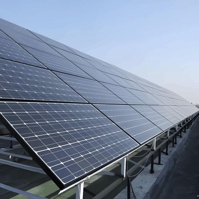
Renewable Energy Power Stations: Particularly suitable for step-up substations in wind farms and photovoltaic power plants, helping to mitigate the impact of fluctuating renewable energy output on grid voltage.
Urban Power Grids and Infrastructure: Supplies power to critical load areas such as commercial districts, hospitals, and data centers, ensuring power quality and preventing damage to sensitive equipment from voltage instability.

Related Products
-
10kV 35kV Oil-Immersed Electric Furnace Transformers
-
100kVA 15kV 3Phase Oil-immersed distribution transformer
-
100kVA 15kV Oil-immersed distribution transformer three-phase
-
2500kVA 11kV Oil-immersed distribution transformer three-phase
-
Oil Distribution Transformer up to 3150 kVA
-
Minera MP Oil Immersed Medium Power Transformers
-
33kV Three-phase Oil-immersed Power Distribution Transformer

Related Knowledges
-
 How to Handle Overheating of Busbar Isolating SwitchesOverheating of Busbar Isolating Switches: Causes and Handling ProceduresOverheating of busbar isolating switches is a common electrical equipment defect. If not addressed promptly, the situation can severely deteriorate during a system short circuit—when high short-circuit current flows through the overheated point, potentially causing contact melting or even destruction of the switch.When overheating of a busbar isolating switch is detected, follow these steps for safe handling: Report the defeFelix Spark11/08/2025
 -
 Manual or Electric Isolator Not Opening? Here’s What to DoIsolating Switch: Definition and OverviewAn isolating switch (or disconnector) is a switching device primarily used for isolating power sources, switching operations (bus transfer), and making or breaking small-current circuits. It has no arc-quenching capability.When in the open position, there is a specified insulation distance between contacts and a clearly visible disconnection indicator. When in the closed position, it can carry the normal operating current and, for a specified duration, thGarca11/08/2025
 -
 Why Capacitor Bank Isolators Overheat & How to FixCauses of High Temperature in Isolating Switches of Capacitor Banks and Corresponding SolutionsI. Causes: OverloadThe capacitor bank is operating beyond its designed rated capacity. Poor ContactOxidation, loosening, or wear at contact points increases contact resistance. High Ambient TemperatureElevated external environmental temperatures impair the switch’s ability to dissipate heat. Inadequate Heat DissipationPoor ventilation or dust accumulation on heat sinks hinders effective cooling. HarmonFelix Spark11/08/2025
 -
 Analysis of Isolating Switch Applications in Generator Neutral Grounding Resistor CabinetsApplication of Isolating Switches in Generator Neutral Grounding Resistor CabinetsIsolating switches are commonly installed in NS-FZ generator neutral grounding resistor cabinets. They provide a clearly visible disconnection point, ensuring the safety of maintenance and testing personnel. However, as high-voltage devices without arc-quenching capability, isolating switches must only be operated when the circuit is de-energized—i.e., under no-load conditions.The primary function of an isolating sEcho11/08/2025
 -
 Centralized vs Distributed Solar Power: Key DifferencesDifferences Between Centralized and Distributed Photovoltaic (PV) Power PlantsA distributed photovoltaic (PV) power plant refers to a power generation system that consists of multiple small-scale PV installations deployed across various locations. Compared to traditional large-scale centralized PV power plants, distributed PV systems offer the following advantages: Flexible Layout: Distributed PV systems can be flexibly installed based on local geographic conditions and electricity demand—in divEcho11/08/2025
 -
 Selection Principles and Considerations for Low-Voltage Electrical ApparatusHow to Select Low-Voltage Electrical Apparatus: Two Key Principles and Four Important ConsiderationsWhen selecting low-voltage electrical devices, two fundamental principles must be followed: safety and economy. Additionally, there are several critical factors to consider. Those unfamiliar with the process should refer to the guidelines below.I. Two Core Principles for Selecting Low-Voltage Electrical Apparatus Safety PrincipleThe selected low-voltage devices must operate accurately and reliablyJames11/08/2025
Related Solutions
-
 PMU High precision distribution line protection automation systemPMU distribution line protection automation system is a new line distribution automation system.for slove presentproblem especially of earth fault. which is base on a Distribution Network Synchronous Phasor Measurement-μPMU.PMU (phasor measurement unit), A stand-alonedevice or module. The voltage/current samplingdata are all with a BDS/GPS timestamp accurateto US level.Basic functions:• Phasor: amplitude, phase Angle,• Frequency (f) and Frequency Variation (△f/△t)&muRockwill11/28/2024
 -
 Intelligent Operation Solution for 12kV Vacuum Circuit Breakers: Integrating Real-time Monitoring & Lifetime OptimizationⅠ. Equipment Operation & MaintenanceIntelligent Monitoring System IntegrationMulti-parameter Real-time Monitoring: Embedded sensors (temperature, displacement, Hall effect current sensors) track contact temperature rise, mechanical characteristics (opening/closing speed, overtravel), coil current, and partial discharge signals. Data undergoes preprocessing via edge computing prior to cloud upload.Lifetime Prediction Model: Dynamically evaluates remaining lifespan using electrical wear dataRockwill06/10/2025
 -
 SF6 Circuit Breaker Solutions for Outdoor Installation (Anti-Pollution & Seismic Resistance)I.Core Challenges in Outdoor InstallationIn high-voltage transmission and distribution systems, SF6 circuit breakers are exposed to complex outdoor environments for extended periods, facing the following critical issues:Pollution & Insulation DegradationDust, salt fog, and industrial pollutants in outdoor environments easily adhere to equipment surfaces. In coastal or industrial areas, pollution levels may reach Class IV, resulting in insufficient creepage distance and triggering flashoRockwill05/12/2025


