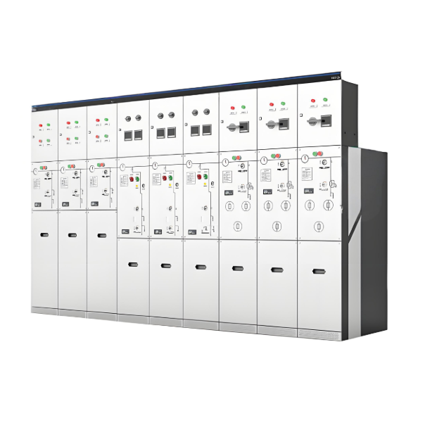
16.5kV–27 kV Medium Voltage Metal-Clad Switchgear

Key attributes
| Brand | POWERTECH |
| Model NO. | 16.5kV–27 kV Medium Voltage Metal-Clad Switchgear |
| Rated voltage | 27kV |
| Series | Masterclad™ |
Product descriptions from the supplier
Description
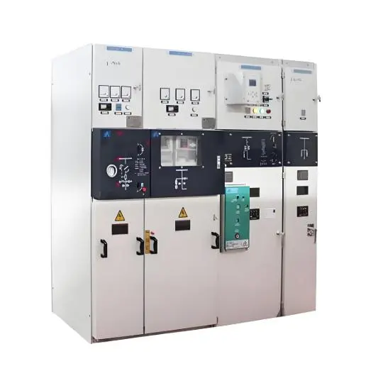
The quality of Square D Masterclad™ Medium Voltage Metal-Clad Switchgear stems from a design and manufacturing process that focuses on long-term switchgear performance with the highest degree of reliability. Reliable performance and safety are enhanced by the rugged construction of Masterclad switchgear. The switchgear consists of individually grounded, compartmentalized steel structures to protect operating personnel and equipment.
Masterclad switchgear components include available state-of-the-art electronics like ION power quality monitoring and EASERGY protective relays, EcoStruxure™, integrated racking, and automatic throwover systems.
Standardization of the design incorporates a series of basic modular units, control packages, and instrumentation. For most switchgear ratings, circuit configurations, and functions, one basic size unit is used. These features provide application flexibility, versatility, and efficiency, reducing lead time and engineering time spent on planning and laying out the switchgear.
Standard features
Air-insulated switchgear defined by ANSI C37.20.2
UL listed equipment
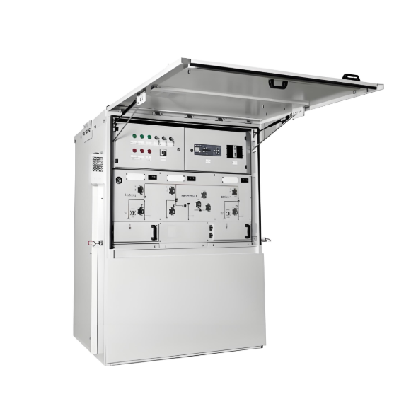
Indoor and outdoor options with one or two high breaker arrangements
Also available as arc resistant structurestype 2B for 5 and 15 kV class
Removable (drawout) circuit breaker
Compartmentalized enclosure with grounded barriers
Isolated low voltage compartment
Automatic gear driven shutters
Automatic shutters in VT, CPT, and fuse truck compartments
Epoxy insulated busbars
Mechanical interlocks
Disconnect style instrument transformers
Continuous grounded breaker and auxiliary trucks, in and between test/disconnected and connected positions
Parameter
16.5–27 kV
1200–2000 Amperes Continuous Ratings
16, 25, and 40 kA Symmetrical Interrupting Capacity
125 kV BIL, peak (impulse) dielectric withstand
60 kV, rms 1 minute 60 Hz dielectric withstand
NEMA Type 1 – Indoor enclosure
Structural diagram

27 kV Layout Dimensions


Related Products
-
RMR Series Gas-Insulated Metal-enclosed Switchgear

-
12/24kV SF6 GIS for Secondary Distribution/Ring Main Unit
-
17.5kV SF6 GIS for Secondary Distribution / Ring Main Unit
-
40.5kV series SF6 gas-insulated switchgear
-
11kV SF6 MV Ring Main Unit Switchgear

-
10.5kV 11kV 11.5kV 12kV Solid Insulated Ring Main Unit/Switchgear source manufacturer
-
13.2kV 12kV 14.5kV 15kV 21.9kV Solid insulation switchgear/Ring Main Unit direct supply
Related Knowledges
-
 Main Transformer Accidents and Light Gas Operation Issues1. Accident Record (March 19, 2019)At 16:13 on March 19, 2019, the monitoring background reported a light gas action of No. 3 main transformer. In accordance with the Code for Operation of Power Transformers (DL/T572-2010), operation and maintenance (O&M) personnel inspected the on-site condition of No. 3 main transformer.On-site confirmation: The WBH non-electrical protection panel of No. 3 main transformer reported a Phase B light gas action of the transformer body, and the reset was ineff02/05/2026
 -
 Faults and Handling of Single-phase Grounding in 10kV Distribution LinesCharacteristics and Detection Devices for Single-Phase Ground Faults1. Characteristics of Single-Phase Ground FaultsCentral Alarm Signals:The warning bell rings, and the indicator lamp labeled “Ground Fault on [X] kV Bus Section [Y]” illuminates. In systems with a Petersen coil (arc suppression coil) grounding the neutral point, the “Petersen Coil Operated” indicator also lights up.Insulation Monitoring Voltmeter Indications:The voltage of the faulted phase decreases (in01/30/2026
 -
 Neutral point grounding operation mode for 110kV~220kV power grid transformersThe arrangement of neutral point grounding operation modes for 110kV~220kV power grid transformers shall meet the insulation withstand requirements of transformer neutral points, and shall also strive to keep the zero-sequence impedance of substations basically unchanged, while ensuring that the zero-sequence comprehensive impedance at any short-circuit point in the system does not exceed three times the positive-sequence comprehensive impedance.For 220kV and 110kV transformers in new constructi01/29/2026
 -
 Why Do Substations Use Stones, Gravel, Pebbles, and Crushed Rock?Why Do Substations Use Stones, Gravel, Pebbles, and Crushed Rock?In substations, equipment such as power and distribution transformers, transmission lines, voltage transformers, current transformers, and disconnect switches all require grounding. Beyond grounding, we will now explore in depth why gravel and crushed stone are commonly used in substations. Though they appear ordinary, these stones play a critical safety and functional role.In substation grounding design—especially when multiple gr01/29/2026
 -
 Why Must a Transformer Core Be Grounded at Only One Point? Isn't Multi-Point Grounding More Reliable?Why Does the Transformer Core Need to Be Grounded?During operation, the transformer core, along with the metal structures, parts, and components that fix the core and windings, are all situated in a strong electric field. Under the influence of this electric field, they acquire a relatively high potential with respect to ground. If the core is not grounded, a potential difference will exist between the core and the grounded clamping structures and tank, which may lead to intermittent discharge.I01/29/2026
 -
 Understanding Transformer Neutral GroundingI. What is a Neutral Point?In transformers and generators, the neutral point is a specific point in the winding where the absolute voltage between this point and each external terminal is equal. In the diagram below, pointOrepresents the neutral point.II. Why Does the Neutral Point Need Grounding?The electrical connection method between the neutral point and earth in a three-phase AC power system is called theneutral grounding method. This grounding method directly affects:The safety, reliabilit01/29/2026
Related Solutions
-
 Core Value and Innovative Applications of 12kV Medium Voltage Switchgear in Smart SubstationsWith the Rapid Development of Smart Grids and the Integration of Renewable Energy Medium Voltage (MV) Switchgear, as the core power distribution equipment in substations, directly determines the stability of the power system through its reliability, intelligence, and space efficiency. This article delves into the key technologies, scenario-specific solutions, and practical benefits of Medium Voltage Switchgear in substations.Core Requirements for Substation ScenariosHigh Reliability Requirements06/12/2025
 -
 Withdrawable 12kV Medium Voltage Switchgear: The Indispensable Pivot of Flexibility and Safety in Smart GridsAt the core of medium-voltage power distribution systems in industrial facilities, commercial complexes, and data centers, switchgear acts as a silent commander, governing the lifeline of electrical flow. Among various solutions, Withdrawable Switchgearhas become synonymous with reliability in modern MV systems due to its unique design philosophy. Compared to fixed switchgear, its "withdrawable" feature delivers compelling advantages, setting new benchmarks for operational efficiencyand per06/12/2025
 -
 Core Dilemma in Southeast Asia 12kV Medium Voltage SwitchgearSoutheast Asia’s rapidly growing power demand (GDP growth >5% annually) combined with extreme climatic conditions—high temperature, humidity, and salt spray corrosion—necessitates balancing lifecycle costs with climate resilience in switchgear selection. This article analyzes the optimal cost-performance solutions between GIS and AIS.I. GIS vs. AIS Cost Comparison Model (Southeast Asia Context)1. Initial Investment Costs2. Long-Term Operational CostsGIS Advantages:Ext06/12/2025


