Bijî her çavkaniya raporê yên elektrîn, transformatorkanên tenzîyeyên elektronî (EVTs), wek cihazên pîvanî pîvandinê yên raporê yên elektrîn, stabîlîya wekari û parastîna wan ji bo serparastkirina wekari û stabîla raporê yên elektrîn bîcik e. Parastina kompatibîlikê ya elektromagnetîk (EMC) wek yek ji agahiyên nîvendî yên EVTs, tevgera ku ciha dikare werbikar bike di navçeyên elektromagnetîkên rakîn de û ew ne ku jî dibe ku ciha din derbas bike. Kirûbarkirina li ser bîcik û projeksiyona EMC ya EVTs piştgirî ye ku stabîlîya hêrgender û parastina raporê yên elektrîn bêdilîne.
1 Têkeftina Kompatibîlikê Elektromagnetîk ê ya Transformatorkanên Tenzîyeyên Elektronî
1.1 Pêşnûma û Daxwazên Kompatibîlikê Elektromagnetîk
Kompatibîlikê elektromagnetîk (EMC) têgala ku ciha an sistem dikare werbikar bike di navça elektromagnetîkê de û ne ku jî dibe ku ciha din derbas bike. Ji bo EVTs, wan hewce ne ku destpêka pîvandinê ûst be di navçeyên elektromagnetîkên rakîn de û ne ku jî dibe ku ciha din derbas bike. Dema ku EVTs dizayn û hejmar kirin, parasta EMC hatiye pêşniyar kirin û rêzikarên parastina vê yekê hatine saz kirin.
1.2 Bersiva Wekariya Transformatorkanên Tenzîyeyên Elektronî
EVTs berîva induksiyonê elektromagnetîk û teknolojîya pîvandinê ya elektronî ya pîvanî da ku sinyalên tenzîyeyên mezin di raporê yên elektrîn de biguherînin da ku sinyalên tenzîyeyên bi tenzîyeyên mezindar bêne. Wan dema ku hundimîn ji sensora primâr, cirkulla guhertina duyemîn û unita pêşandina sinyalê. Sensora primâr masul e ku sinyalên tenzîyeyên mezin biguherîne da ku sinyalên kêm tenzîyeyên proporsîyonel bi tenzîyeyên primâr bêne; cirkulla guhertina duyemîn sinyalên kêm bêtguherîne da ku sinyalên standard digital/analog bikin; unita pêşandina sinyalê pêşandina pîvandinê û stabîlîya wê biguherîne di operasyonan de wanê şîl, zêdekirin û pêşandina. EVTs din ku hundimîn formên din, wek transformatorkanên tenzîyeyên elektronî yên pîvandinê kanalen/yên tenzîyeyên mezin, transformatorkanên amperajên elektronî yên pîvandinê kanalen/yên amperaj, an transformatorkanên integreyên wek şîkil 1 ku heman tenzîyeya yek kanal, amperaj û nîrvana mîna bêtguhertin.
1.3 Analîza Harassmenda Elektromagnetîk û Rezandînî Elektromagnetîk
EVTs di navça elektromagnetîkê de heste ku ji harassmentên elektromagnetîkên derve, wek lînek û overvoltages transîentîn lê vegere, ku dikarin pirsgirekan çêkerin da ku pîvandinê çêker û data nistabîl bêne; heman, harmonîkên paqît û radyasyonê elektromagnetîkên ku bi girtina EVTs xwe çêkerin dikarin jiyan derbas bike. Dema ku EVTs dizayn kirin, mesele harasementa elektromagnetîk û rezandînî elektromagnetîk hewce ne ku bi girîngî pêşniyar bikin û rêzikarên supresyon û parastina saz bikin.
Testa performansa EMC ya EVTs qopê reyî ye ku bêdilîne stabîlîya û pîvandiya wê di karina faktî de. Li ser bêdanîya anti-interference û classifîkirina standartên evalûasyonan di Class A û Class B de:
2 Analîza Testên Performansa Kompatibîlikê Elektromagnetîk ê ya Transformatorkanên Tenzîyeyên Elektronî
2.1 Naverok û Standartên Evalûasyon
Class A: Divê ku meta EVTs ji harassmentên elektromagnetîk hate heste, pîvandinê çêker û sinyalê tenzîyeyê ya deroja hatiye di navçeyên specifikasyon de û ne ku jî dibe ku monitor û kontrola raporê yên elektrîn çêker bêne.
Class B: Diha ku pîvandinê çêker (parti ne ku li ser parastina ye) ya EVTs hate heste, lê divê ku ne ku jî dibe ku funksiyonên parastina çêker bêne, û ciha nehatiye reset/restart kirin; sinyalê tenzîyeyê divê ku di nav 500V de kontrol kirin da ku ne ku jî dibe ku raporê yên elektrîn derbas bike.
2.2 Testên Interference Conducted
Interference conducted di navça pathên conductive de, wek tîr û pipe metalî, bêne û yek ji navberên serekan harassmentên elektromagnetîk yên ku EVTs heste. Ew du testan dide:
Testa Burst Fast Transient/Electrical: Şîmilîya harassmenta transîentîn (bi spektraya frekansî mezin) diha ku îndukanan lê vegere, wek relay û contactors, hate heste. Burst fast-transient ê bi EVT hate heste, stabîlîya û pîvandinê ya sinyalê tenzîyeyê ya deroja şopand in, û bêdanîya anti-interference evalûe kirin.
Testa Immunity Surge (Impact): Şîmilîya overvoltages/overcurrents transîentîn (bi energy mezin û duration kêm) diha ku switch operations û lînek hate heste. Surge voltage bi amplitudê teyîn birî bi EVT hate heste da ku test kapasitivîya û stabîlîya performansa ciha bêne.
2.3 Testên Interference Radiated
Ew du testan dide da ku şîmilîya interference în navcheyên elektromagnetîkên din:
Testa Immunity Magnetic Field Power Frequency: Magnetic field bi intensity teyîn birî bi EVT hate heste, stabîlîya û pîvandinê ya sinyalê tenzîyeyê ya deroja şopand in, û bêdanîya anti-interference di navça magnetic field power frequency de evalûe kirin.
Testa Immunity Magnetic Field Damped Oscillatory: Şîmilîya magnetic field damped oscillatory (bi attenuation fast û frekansa mezin) diha ku disconnector di high-voltage substation de bus switching hate heste. Magnetic field teyîn birî bi EVT hate heste da ku stabîlîya performansa pîvandinê test kirin.
Testa Immunity Pulse Magnetic Field: Şîmilîya pulse magnetic field (bi rise fast û peak value mezin) diha ku lînek bi componentên metalî hate heste. Pulse magnetic field bi EVT hate heste da ku şopand in e ku insulation performance û pîvandinê ya ciha çêker bêne.
Testa Immunity Radio Frequency Electromagnetic Field: Şîmilîya parasitic radiation ji electromagnetic sources industrial, radio broadcasts/mobile communication base stations, etc. Radio frequency electromagnetic field bi intensity teyîn birî bi EVT hate heste, stabîlîya sinyalê deroja şopand in, û bêdanîya anti-interference evalûe kirin.
3 Prinsipên Dizaynê Kompatibîlikê Elektromagnetîk ê ya Transformatorkanên Tenzîyeyên Elektronî
3.1 Prinsipên Dizaynê Cirkula
Dizayna Ground Floating: Teknolojî ground floating bikar bînin da ku signal line ciha ji chassis izolate bikin, blockage coupling of interference currents on the chassis to the signal circuit, reduce noise, and improve signal accuracy and stability.
Layout Wiring Reasonable: Layout of power supplies, grounds, and signal lines optimize. Reduce parallel distribution of lines and minimize coupling interference between lines through methods such as layered wiring and orthogonal wiring.
Design Filter Capacitor: Configure filter capacitors at the input end of the module power supply. Select the capacitors based on factors such as capacitance value, voltage resistance, and frequency characteristics to filter out high-frequency noise and interference introduced by the power supply.
Low-level Logic Design: Give priority to low-level logic devices (such as 3.3V level devices) to avoid unnecessary high logic levels, reduce circuit power consumption and the generation of high-frequency interference.
Rise/Fall Time Control: Select the slowest rise/fall time allowed by the circuit function to suppress unnecessary high-frequency components, reduce high-frequency noise in the circuit, and improve signal stability and accuracy.
3.2 Internal Structure Design Principles
Fully Enclosed Shielding Structure: The chassis shell adopts a fully enclosed shielding design to ensure good contact and grounding of each surface, effectively block external electromagnetic field interference, and protect the internal electronic circuits.
Minimization of Exposed Wiring: Shorten the length of exposed wiring in the chassis by optimizing the layout and reasonably arranging components to reduce electromagnetic radiation and coupling interference.
Group Bundling of Wires: Bundle wires according to signal types (separate digital signals and analog signals), and keep a certain distance to reduce the mutual influence between wires and improve signal clarity and accuracy.
Conductive Adhesive Bonding: Use conductive adhesive for bonding at the chassis interface to ensure electrical connection and shielding effect, reduce contact resistance, and improve shielding efficiency.
4 Strategies for Improving Electromagnetic Compatibility Performance of Electronic Voltage Transformers
4.1 Anti - interference Design of Power Ports
Install Power Filters: Select suitable power filters according to the rated power and working environment of the EVT, and install them close to the power inlet to filter out high - frequency noise and transient pulses and ensure power purity.
Adopt Redundant Power Design: Configure multiple power modules. When a single module fails, the remaining modules quickly take over the power supply, improving the power supply reliability, anti - interference ability, and overall stability of the EVT.
Strengthen Shielding and Grounding of Power Lines: Use shielded cables to wrap power lines to reduce electromagnetic radiation and coupling; ensure good grounding of the lines, introduce interference currents into the ground, and avoid damaging the EVT.
4.2 Electrostatic Discharge Protection of Signal Ports
Install Transient Harassment Absorption Devices: Select suitable transient voltage suppression diodes (TVS), varistors, and other devices. These devices can quickly absorb energy during electrostatic discharge, control the voltage within a safe range, and protect internal electronic components.
Adopt Differential Signal Transmission Method: Divide the signal into positive and negative channels for differential transmission. Use the signal difference between channels to extract effective information, resist common - mode interference, improve signal transmission quality, and reduce the interference of electrostatic discharge.
4.3 Optimization of Chassis Shielding Performance
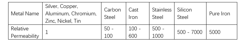
Select High - Permeability Materials: Give priority to materials with high magnetic permeability such as iron plates to make the chassis, enhance the magnetic field shielding ability, absorb and disperse magnetic field energy, and reduce interference to the inside of the EVT (the relative magnetic permeability of metals is shown in Table 1).
Optimize Chassis Structure Design: Adopt a fully enclosed shielding structure to ensure good contact and grounding of each surface of the chassis and enhance the shielding effect.
Strengthen Chassis Grounding Treatment: Ensure a reliable grounding connection between the chassis and the ground, introduce interference currents into the ground, and improve shielding efficiency.
5 Conclusion
This paper conducts in - depth research on the EMC performance of EVTs, proposes principles from the aspects of circuit design and internal structure design, and formulates strategies such as anti - interference design of power ports, electrostatic protection of signal ports, and optimization of chassis shielding. The aim is to improve the anti - interference ability and stability of EVTs in complex electromagnetic environments, ensure their accurate and reliable measurement of voltage signals in power systems, and lay a solid foundation for the safe and stable operation of power systems.


