• Product
  • Suppliers
  • Manufacturers
  • Solutions
  • Free tools
  • Knowledges
  • Experts
  • Communities
Search


Vacuum Circuit Breaker Withstand Voltage Test Guide

Garca
Garca
Campo: Design & Maintenance
Congo

Insulation Withstand Voltage Test Standards for Vacuum Circuit Breakers

The main purpose of the insulation withstand voltage test for vacuum circuit breakers is to verify whether the insulation performance of the equipment under high voltage is qualified, and to prevent breakdown or flashover accidents during operation. The test process must be strictly carried out in accordance with power industry standards to ensure equipment safety and power supply reliability.

Test Objects

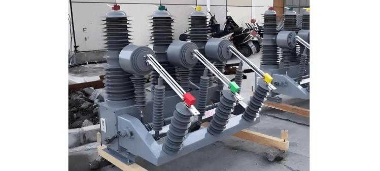
The test objects include the main circuit, control circuit, secondary circuit, insulating support components, and the enclosure body of the circuit breaker.

  • The main circuit includes live parts such as moving contacts, fixed contacts, and conductive rods.

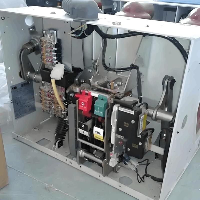
  • The control circuit includes low-voltage components such as trip and close coils, auxiliary switches, etc.

Test Voltage Standards

Power frequency withstand voltage test reference values:

  • Main circuit of 10kV circuit breaker — 42kV / 1 minute

  • Main circuit of 35kV circuit breaker — 95kV / 1 minute

  • Between secondary circuit and enclosure — 2kV / 1 minute

DC withstand voltage test is generally twice the power frequency voltage, with a duration of 1 minute.

(Reference standards: DL/T 596-202 Preventive Test Code for Electrical Equipment, GB 501-201 Code for Handover Testing of Electrical Equipment in Electrical Installation Projects)

Test Conditions

Ambient temperature within 5–40°C, relative humidity ≤80% RH; the equipment is in the open position and not energized; all exposed conductive parts are reliably grounded; the test equipment must have been calibrated and be within its validity period.

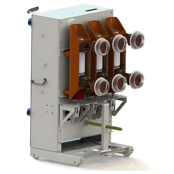
VCB..jpg

Implementation Steps

1. Safety Preparation
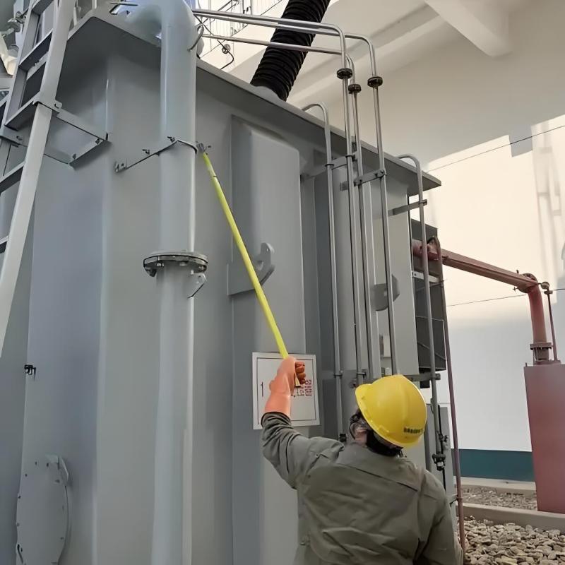
Disconnect all external power sources and verify that there is no voltage. Close the grounding switch and hang warning signs. Remove connections unrelated to the test, and use dedicated shorting wires to short-circuit the three phases A/B/C of the circuit breaker.

2. Wiring Method
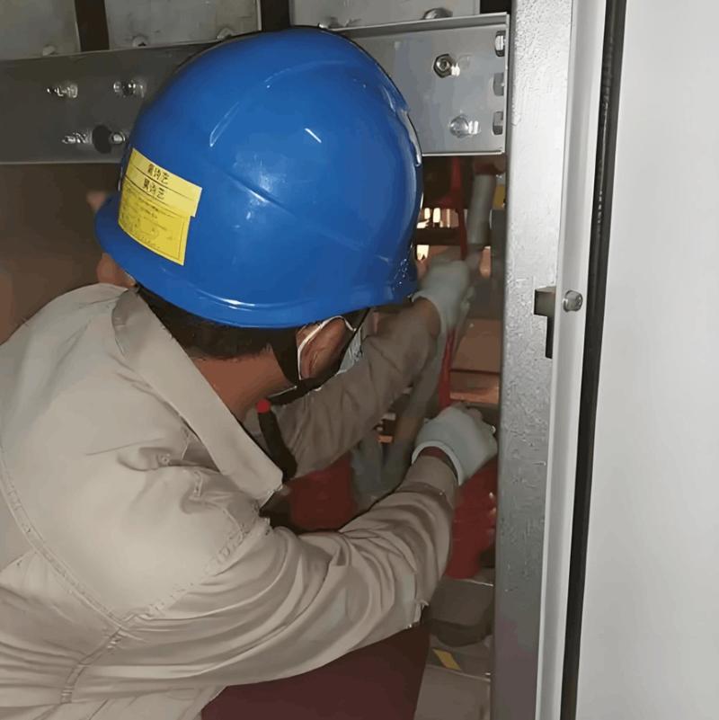
Connect the high-voltage terminal of the withstand voltage tester to the main circuit terminals of the circuit breaker, and connect the grounding terminal to the grounding bolt on the circuit breaker's enclosure. For secondary circuit testing, use insulating tape to cover exposed contacts, and clamp the high-voltage output lead of the tester to the secondary terminal block.

3. Voltage Rising Process
Raise the voltage at a rate of 1kV per second to the specified voltage value, during which observe changes in leakage current. After the voltage stabilizes, start timing. After the specified time has elapsed, reduce the voltage uniformly to zero. If abnormal discharge sounds, sudden current changes, or insulation gas leakage occur during the test, immediately terminate the test.

4. Result Judgment
The test is considered qualified if the leakage current does not exceed 100μA during the test and no breakdown or flashover occurs. Record the initial voltage value, peak leakage current, ambient temperature and humidity data, and perform trend comparison analysis with historical data.

Precautions

  • The test voltage must be corrected when altitude exceeds 100m

  • Equipment that has just been taken out of service must be left stationary for 30 minutes to dissipate heat

  • GIS combined electrical equipment requires overall testing

  • Testing is prohibited when internal gas pressure is abnormal

  • Operators must wear high-voltage insulating boots and protective goggles

Common Problem Handling

  • Obvious discharge sound but no breakdown: Check whether the vacuum degree of the arc extinguishing chamber is below 6.6×10⁻²Pa; replace the vacuum interrupter if necessary.

  • Excessive leakage current: Check whether there are tracking marks on the insulating pull rod; clean dirt from the porcelain insulator surface and retest.

  • Local overheating: Suspend the test and investigate issues such as oxidation on contact surfaces or insufficient spring pressure.

After the test is completed, restore the equipment to its original state, clean the work site, and enter the test data into the equipment operation and maintenance file for reference during the next maintenance. The recommended periodic test cycle is: perform the first test one year after new equipment is put into operation, subsequent tests every 3 years, and for equipment that has been in operation for more than 15 years, shorten the interval to every 2 years.

Dar propina y animar al autor
Recomendado
A Guide to the Latest Transformer Testing Technologies
Transformers come in many types, primarily oil-immersed and dry-type. Their fault manifestations are diverse, but most failures are concentrated in the windings, core, connecting components, and oil contamination. For example, winding insulation damage, open circuits, short circuits, and inter-turn short circuits at connection points. Common external symptoms of transformer faults include severe overheating, excessive temperature rise, abnormal noise, and three-phase imbalance.Routine transforme
Oliver Watts
10/20/2025
Inspection of transformers can be performed without any detection tools.
Transformers are electrical devices that change voltage and current based on the principle of electromagnetic induction. In power transmission and distribution systems, transformers are essential for stepping up or stepping down voltages to reduce energy losses during transmission. For example, industrial facilities typically receive power at 10 kV, which is then stepped down to low voltage via transformers for on-site use. Today, let’s learn about several common transformer inspection methods.1
Oliver Watts
10/20/2025
Why Can't a 10kV VCB Trip Locally?
The inability to manually operate the local mechanical trip of a 10kV vacuum circuit breaker is a relatively common fault type in power system maintenance work. Based on years of field experience, such issues typically stem from five core areas, each requiring troubleshooting based on specific symptoms.Operating mechanism jamming is the most common cause. The tripping process of a circuit breaker relies on mechanical energy released from spring energy storage; if rust, deformation, or foreign ob
Felix Spark
10/18/2025
Vacuum Circuit Breakers for Capacitor Bank Switching
Reactive Power Compensation and Capacitor Switching in Power SystemsReactive power compensation is an effective means to increase system operating voltage, reduce network losses, and improve system stability.Conventional Loads in Power Systems (Impedance Types): Resistance Inductive reactance Capacitive reactanceInrush Current During Capacitor EnergizationIn power system operation, capacitors are switched in to improve power factor. At the moment of closing, a large inrush current is generated.
Oliver Watts
10/18/2025
Enviar consulta
Descargar
Obtener la aplicación IEE Business
Utiliza la aplicación IEE-Business para encontrar equipos obtener soluciones conectarte con expertos y participar en colaboraciones de la industria en cualquier momento y lugar apoyando completamente el desarrollo de tus proyectos y negocios de energía