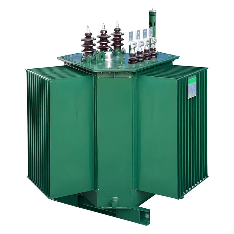
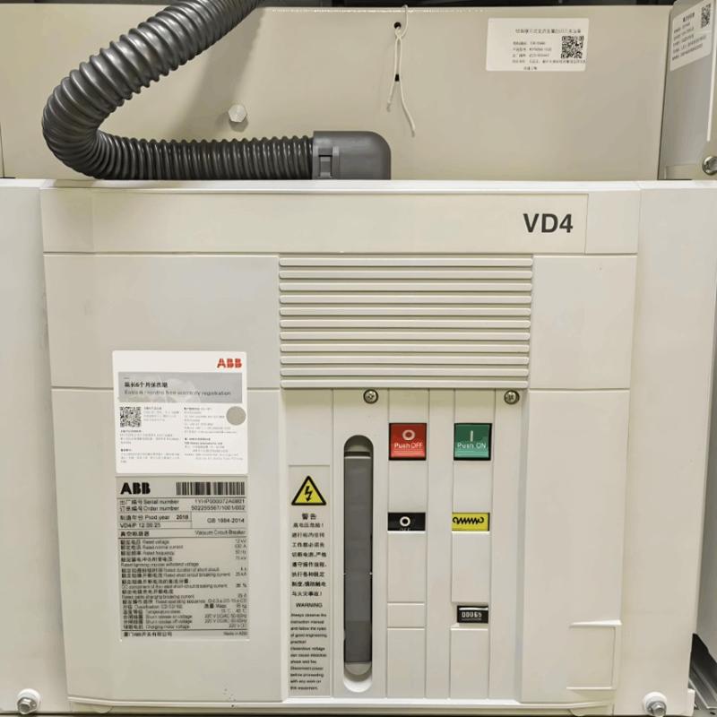
In power systems, low-voltage vacuum contactors are used for remotely connecting and disconnecting circuits, as well as frequently starting and controlling AC motors. They can also form electromagnetic starters together with various protection devices.
Due to their longer service life, higher reliability, and auxiliary switches compatible with electronic equipment, low-voltage vacuum contactors can fully replace traditional air AC contactors. They are applied in important scenarios across sectors such as mining, metallurgy, building materials, chemical engineering, petroleum, and heavy industry, where their characteristics and advantages are more prominently demonstrated.
1. Structure and Working Principle of Low-Voltage Vacuum Contactors
1.1 Structure of Low-Voltage Vacuum Contactors
A single-pole contactor serves as the basic unit, which can be assembled into 1-pole, 2-pole, ..., n-pole contactors. In the open state, the two contacts of the vacuum interrupter are separated by 1.5–1.8 mm. This separated state of the contacts is maintained by the pressure spring in the drive system. For contactors with a current rating of 800–1600 A, the contact opening distance is approximately 3.5 mm.
When the control power supply is turned on, the electromagnet does work against the pressure spring, releasing the moving contact rod. The moving contact rod closes the contacts by means of atmospheric pressure acting externally on the vacuum interrupter. The electromagnet is designed as a DC electromagnet with an energy-saving resistor. When an AC control power supply is used, the AC power is rectified by a rectifier module, and the DC power is then used to drive the mechanism to operate. Each drive mechanism is equipped with a rectifier module when operating under AC voltage.
1.2 Electrical Principle
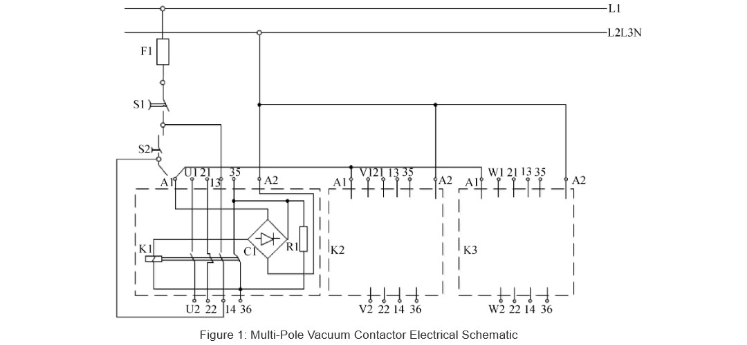
This article only introduces vacuum contactors with AC control voltage. The electrical principle of a multi-pole vacuum contactor is shown in Figure 1. U1/U2, V1/V2, and W1/W2 are the main circuit contacts; A1/A2 are the power input contacts of the control circuit.
2. Application of Low-Voltage Vacuum Contactors in DF100A Shortwave Transmitters
2.1 Function of Low-Voltage Vacuum Contactors
The EVS630 low-voltage vacuum contactor (equipment number: 4A5K1) is used in the DF100A shortwave transmitter. The high-voltage control circuit is shown in Figure 2. The main function of 4A5K1 is as follows: after the high-voltage closing button 6S7 is pressed, the AC 230V control voltage is delivered to the 4A5K1 (a, b) contacts, enabling 4A5K1 to pull in. It maintains this state through the self-holding function of 4A5K1 (3, 4). The main contacts transmit the three-phase AC 380V voltage to the modulation transformer, thereby providing the corresponding voltage for 48 power modules. Meanwhile, a control signal is sent to the nine units via 4A5K1 (11, 12).

2.2 Daily Maintenance
Perform daily cleaning to ensure the low-voltage vacuum contactor has a good working environment without dust accumulation.
Measure the temperature at regular intervals. If the temperature is too high, promptly check and fasten the terminal screws.
Regularly clean the dust between the electromagnet and the armature to prevent the armature from jamming during use.
For the backup low-voltage vacuum contactor, connect 220VAC lighting power to its (a, b) contacts to make it pull in. Use a multimeter to check whether each contact is in good contact, so as to ensure the backup is in good condition and available for use.
2.3 Common Fault Analysis and Handling
(1)After applying high voltage, the interlock No. 4 indicator light on the modulator 9A5 board does not light up; the meter value of the pre-final stage is normal, the screen grid current of the high-final stage is normal, but there are no meter values for the plate current and plate voltage of the high-final stage, and there is no power output; the non-operating indicator light on the 9A4 board is on, and the module indicator lights on the status board are normal.
Fault Analysis: The control circuit of the interlock No. 4 indicator light is shown in Figure 3. It is controlled by a set of contacts (9, 3) of the internal interlock relay 1K32 controlled by the modulator and the auxiliary contacts (11, 12) of the high-voltage second-stage electromagnetic switch 4A5K1. When high voltage is applied to the transmitter, 4A5K1 closes, and its normally open auxiliary contacts close at the same time; the optocoupler U6 emits light, and the interlock No. 4 indicator light on the modulator 9A5 board lights up.
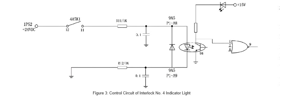
If there is a problem with the mechanical structure of the electromagnetic switch itself, or the auxiliary contacts have poor contact (resulting in the main contacts closing but the auxiliary contacts (11, 12) having poor contact), the interlock No. 4 indicator light on the 9A5 board will not light up, a non-operating command signal will be generated, the modulator will be locked, and the transmitter will have no plate voltage, screen grid voltage or power output.
Fault Handling: If a backup is available, switch to the backup. If there is no backup, urgently short-circuit the transmitter terminals (1TB10-18, 1TB10-1). After the broadcast, clean the (11, 12) contacts. To improve reliability, unused idle contacts can be connected in parallel.
(2)When high voltage is applied to the transmitter, the pull-in sound of the first gear and the second gear can be heard; shortly after, both the first gear and the second gear drop simultaneously, and the high-voltage second gear cannot maintain its state (self-holding failure).
Fault Analysis: Poor contact of the high-voltage second-stage electromagnetic switch 4A5K1 (3, 4) causes the high-voltage circuit to fail to self-hold.
Fault Handling: If a backup is available, switch to the backup. If there is no backup, urgently short-circuit (4A5TB2-14, 4A5TB2-19).
(3)When high voltage is applied to the transmitter, the high-voltage first gear can be engaged, but the second gear cannot; shortly after, the first gear drops, and the screen grid current of the high-final stage is overloaded.
Fault Analysis: The current-limiting resistor of the starting coil in one phase of the high-voltage second-stage electromagnetic switch 4A5K1 is damaged.
Fault Handling: If a backup is available, switch to the backup. If there is no backup, urgently replace 4A5K1.
(4)In the high-power state, the pre-final stage is basically normal; the plate current of the high-final stage decreases, the plate voltage increases, and some power modules are turned off.
Fault Analysis: The vacuum interrupter contacts in one phase of 4A5K1 are burned out.
Fault Handling: If a backup is available, switch to the backup. If there is no backup, urgently replace 4A5K1.
(5)When applying high voltage, the first gear is normal; when the second gear is engaged, the plate control circuit breaker 1CB18 trips, and high voltage cannot be applied.
Fault Analysis: The rectifier bridge of 4A5K1 is broken down.
Emergency Handling: If a backup is available, switch to the backup. If there is no backup, urgently replace 4A5K1.
3. Conclusion
During the use of the EVS630 low-voltage vacuum contactor in the DF100A shortwave transmitter, in addition to conducting daily inspection and maintenance, it is also necessary to test the temperature of its main phase terminal screws regularly during operation. An infrared temperature gun or temperature patches can be used for observation. Continuously accumulate data to grasp the inspection and maintenance cycle.


