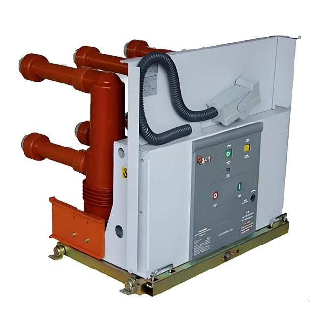
Vacuum Circuit Breakers for Capacitor Bank Switching

Reactive Power Compensation and Capacitor Switching in Power Systems
Reactive power compensation is an effective means to increase system operating voltage, reduce network losses, and improve system stability.
Conventional Loads in Power Systems (Impedance Types):
Resistance
Inductive reactance
Capacitive reactance
Inrush Current During Capacitor Energization
In power system operation, capacitors are switched in to improve power factor. At the moment of closing, a large inrush current is generated. This occurs because, during the first energization, the capacitor is uncharged, and the current flowing into it is limited only by the loop impedance. Since the circuit condition is close to a short circuit and the loop impedance is very small, a large transient inrush current flows into the capacitor. The peak inrush current occurs at the instant of closing.
If the capacitor is re-energized shortly after disconnection without sufficient discharge, the resulting inrush current can be up to twice that of the initial energization. This happens when the capacitor still holds residual charge, and re-closing occurs at the moment when the system voltage is equal in magnitude but opposite in polarity to the capacitor’s residual voltage, resulting in a large voltage difference and thus a high inrush current.
Key Issues in Capacitor Switching
Re-ignition
Re-strike
NSDD (Non-Sustained Destructive Discharge)
Re-ignition is permitted during capacitive current switching tests. Circuit breakers are classified into two categories based on their re-strike performance:
C1 Class: Verified by specific type tests (6.111.9.2), exhibiting low probability of re-strike during capacitive current switching.
C2 Class: Verified by specific type tests (6.111.9.1), exhibiting very low probability of re-strike, suitable for frequent and high-demand capacitor bank switching.
Improving Success Rate of Vacuum Circuit Breakers for Capacitor Switching
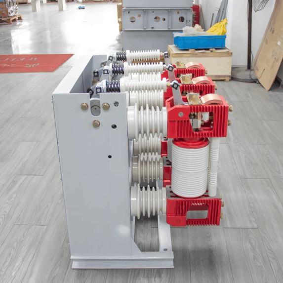
1. Enhance Dielectric Strength of Vacuum Interrupters
The vacuum interrupter is the heart of a vacuum circuit breaker and plays a critical role in successful capacitor switching. Manufacturers must optimize the design and materials to achieve:
Uniform electric field distribution
High resistance to welding
Lower current chopping level
Structural and material improvements are essential to ensure reliable interruption.
2. Control Vacuum Interrupter Manufacturing Process
Minimize and remove burrs during metal part machining; improve surface finish and cleanliness.
Perform ultrasonic cleaning of components before assembly to remove micro-particles.
Control humidity and airborne particles in the assembly room.
Reduce storage time of contact components and assemble promptly to minimize oxidation and contamination.

3. Improve Circuit Breaker Design and Assembly Quality
Ensure mechanical characteristics are within optimal ranges:
Conducting rod alignment and vertical installation to avoid stress.
Proper operating mechanism output energy.
Closing and opening speeds within acceptable limits.
Minimize closing bounce and opening rebound.
Strict control of component quality and assembly precision.
4. No-Load Operation and Conditioning (Burn-in)
After assembly, perform 300 no-load operations to stabilize mechanical characteristics. Conduct voltage and high-current conditioning on the complete switch to eliminate microscopic protrusions and reduce re-ignition rate during capacitor switching.
Parallel capacitor conditioning can rapidly enhance the dielectric strength of the product.
5. Optimize Opening Speed
After interruption, the contact gap of a vacuum circuit breaker must withstand twice the system voltage (2×Um) for up to 13 ms. The contacts must reach a safe open distance within this time. Therefore, the opening speed must be sufficient — especially for 40.5 kV circuit breakers.
6. Conditioning (Aging) of Vacuum Interrupters
Low-effect methods: High-voltage/low-current, low-voltage/high-current, or impulse voltage conditioning have limited effect in reducing re-ignition during capacitor switching.
Effective method: High-voltage and high-current single-phase conditioning can significantly improve performance.
Synthetic test circuit conditioning is also used to simulate real capacitor switching conditions.
For general applications, standard conditioning is applied. However, for capacitor switching duty, special conditioning is required to enhance electrical performance and initial breaking capability.
Conditioning Parameters:
Current Conditioning:
3 kA to 10 kA, 200 ms half-wave, 12 shots per polarity (positive and negative).Pressure Conditioning:
Static pressure (for axial magnetic field contacts): Apply 15–30 kN for 10 seconds.
Make-break conditioning (for transverse magnetic field contacts): Perform closing and opening operations on a test rig simulating actual breaker motion.
Voltage Conditioning:
Apply 50 Hz AC voltage far exceeding rated voltage (e.g., 110 kV for a 12 kV interrupter) for 1 minute.
Test Parameters for Capacitor Switching
GB/T 1984: Back-to-back capacitor banks, inrush current 20 kA, frequency 4250 Hz.
IEC 62271-100 / ANSI Standards:
Capacitor bank switching: current 600 A, inrush 15 kA, frequency 2000 Hz
Switching current 1000 A, inrush 15 kA, frequency 1270 Hz
ANSI allows up to 1600 A for capacitor switching.
After proper conditioning, a 12 kV vacuum circuit breaker can typically pass:
400 A back-to-back capacitor bank switching
630 A single capacitor bank switching
However, for 40.5 kV systems, this is extremely challenging. Common solutions include:
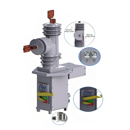
Using SF₆ circuit breakers with gentler interruption characteristics
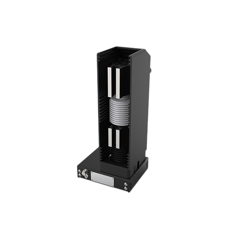
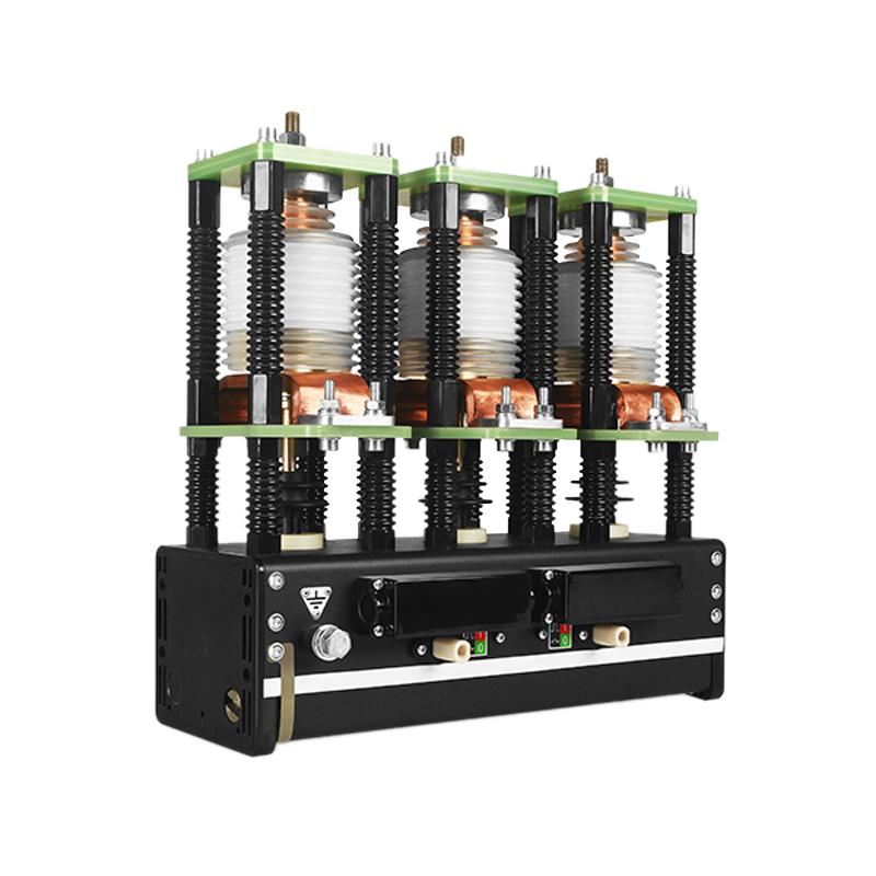
Using double-break vacuum circuit breakers, where two interrupters are connected in series. This significantly improves dielectric recovery strength, allowing it to exceed the rate of transient overvoltage rise during capacitor switching, thereby achieving successful arc extinction.