The core reason is to eliminate circulating currents between parallel conductors, thereby reducing additional losses and lowering temperature rise.
Root cause: Unequal leakage flux linkage
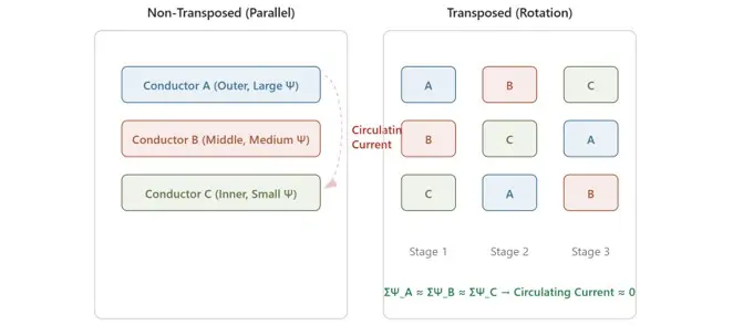
In transformer windings, the leakage magnetic field is non-uniformly distributed in both radial and axial directions. When multiple conductors are connected in parallel to form a single turn, each conductor occupies a different radial position within the winding, and thus links a different amount of leakage flux:
Ψ₁ ≠ Ψ₂ ≠ … ≠ Ψₙ
According to Lenz's law, the induced electromotive forces in the individual conductors are unequal. However, since they are connected in parallel and share the same terminal voltage, circulating currents are generated:
Icirc = ΔE / Rloop
These circulating currents do not perform useful work; they merely generate heat, contributing to additional eddy-current losses. In large-capacity transformers, such losses can account for 20%–40% of the total copper loss.
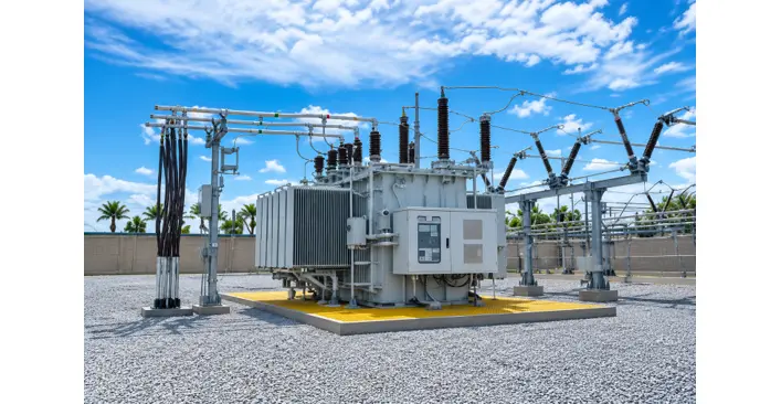
Rockwill S(F) Series 138kV Oil-Immersed Power Transformer
How transposed conductors solve the problem
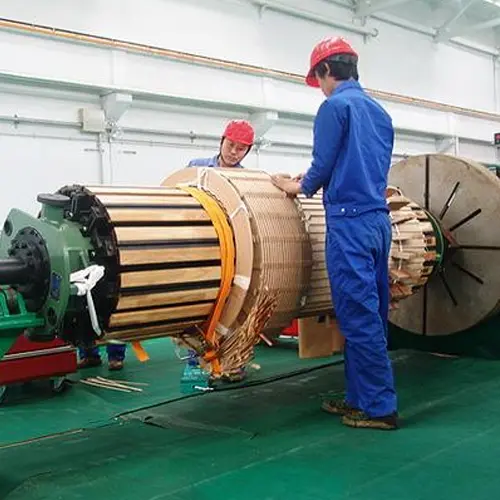
A transposed conductor is constructed so that each individual strand periodically changes its radial position along the entire height of the winding. This ensures that over one complete turn, the total leakage flux linked by each strand becomes approximately equal:
∑Ψᵢ ≈ constant
As a result, the electromotive force differences are eliminated, and circulating currents are reduced to nearly zero.
Main types of transposed conductors
The Rockwill 138 kV transformer employs transposed conductors, which, through their special transposed arrangement of multiple insulated strands, fundamentally and significantly reduce eddy-current and circulating-current losses, thereby greatly enhancing energy efficiency.
In addition, when combined with self-bonding technology, the conductors form a robust, integrated structure that substantially strengthens the winding's ability to withstand short-circuit forces, ensuring equipment safety under fault conditions. Furthermore, this technology offers additional advantages, including a compact structure, excellent heat dissipation, and simplified manufacturing processes—making it a core enabler for achieving high efficiency, reliability, and cost-effectiveness in transformer design.
Edited From:Echo

 Login
Login