With the rapid development of China's economy, the power industry has also gradually expanded in scale, increasing the requirements for both the installed capacity and the single-unit capacity of power transformers. This article provides a brief introduction to four aspects: transformer construction, transformer lightning protection, transformer faults, and transformer noise.
A transformer is a commonly used electrical device capable of converting AC electrical energy. It can transform one form of electrical energy (alternating current and voltage) into another form of electrical energy (with the same frequency of alternating current and voltage). In practical applications, the main function of a transformer is to change voltage levels, making power transmission more convenient.
According to the ratio of output voltage to input voltage, transformers are classified as step-down or step-up transformers. A transformer with a voltage ratio less than 1 is called a step-down transformer, whose primary function is to supply required voltages for various electrical devices, ensuring users receive proper voltage. A transformer with a voltage ratio greater than 1 is called a step-up transformer, which mainly functions to reduce power transmission costs, minimize power losses during transmission, and extend transmission distance.
Transformer Construction
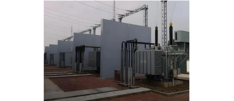
In medium and large-capacity power transformers, a sealed oil tank is provided, filled with transformer oil. The transformer windings and core are immersed in the oil to achieve better heat dissipation. Insulating bushings are used to lead out the windings and connect to external circuits. A transformer mainly consists of the following components: voltage regulating device, main body, outgoing terminal devices, oil tank, protective devices, and cooling devices. The voltage regulating device is divided into on-load and off-load tap changers, essentially a type of tap switch; the main body consists of leads, core, insulation structure, and windings; the outgoing terminal devices include low-voltage and high-voltage bushings; the oil tank comprises accessories (including oil sampling valves, nameplates, drain valves, grounding bolts, and wheels) and the main tank body (including tank bottom, walls, and cover); protective devices include desiccant breathers, gas relays, conservator tanks, oil float relays, oil level indicators, temperature sensors, and safety vents; cooling devices consist of coolers and radiators.
Transformer Noise and Mitigation Measures
Transformers often produce sound during operation, primarily due to electromagnetic forces causing vibration of the main body and magnetostriction in silicon steel sheets under magnetic fields, as well as noise generated by fans and cooling system blowers. The human auditory system can perceive sound only within certain vibration frequencies; when the frequency is between 16 Hz and 2000 Hz, it can be heard. Ultrasound above this range and infrasound below it cannot be perceived. Noise propagates from the core to air, windings, and clamping structures—this is the main transmission path of power transformer noise. Noise can be reduced by lowering magnetic flux density and minimizing magnetostriction in core silicon steel sheets. However, reducing flux density increases core size and the number of silicon steel sheets, raising costs. To reduce noise without increasing costs, adding damping components is effective. For example, placing rubber form-fitting spacers between the low-voltage winding and the core can tighten the winding and provide cushioning. This damping structure helps reduce noise during its propagation.

Transformer Lightning Protection
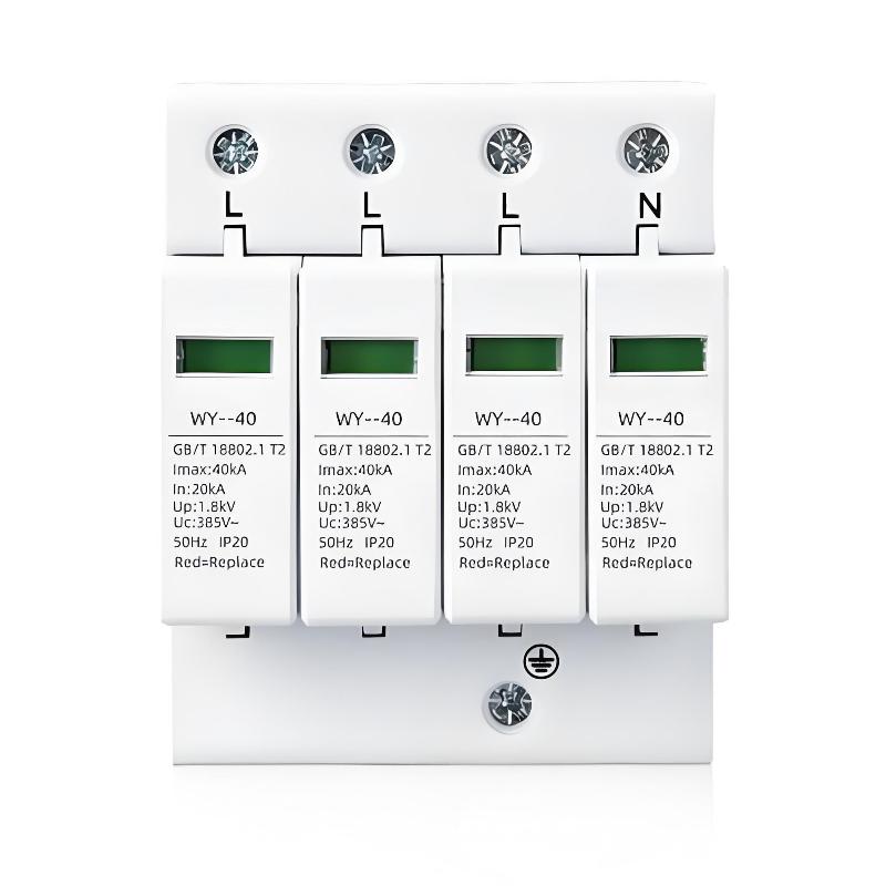
In China, a large number of transformers are damaged annually due to lightning strikes. According to relevant authorities, among damaged 10 kV distribution transformers, 4%–10% are damaged due to lightning. Improper grounding lead connections and incorrect installation of transformer lightning arresters are the main causes of lightning-related damage. Key issues include: separate grounding of high-voltage and low-voltage side arresters and the transformer neutral point; excessively long leads and undersized grounding conductor cross-sections; absence of arresters on the low-voltage side; using the support structure as the grounding conductor for high-voltage side arresters; and failure to conduct preventive tests on arresters.
Transformer Faults
When any of the following changes occur in a transformer, fault analysis can be performed based on its actual operating condition: the transformer causes a power outage due to an accident or experiences phenomena such as an outlet short circuit, but disassembly has not yet occurred; abnormal phenomena occur during operation, forcing operators to shut down the transformer for inspection or testing; during preventive testing, maintenance acceptance, or commissioning under normal power-off conditions, one or more parameter values exceed standard limits. If any of the above situations occur during actual use, the transformer should immediately undergo relevant inspections and tests to ensure it can operate normally.
Steps to Determine the Presence of a Fault:
First, determine the possibility of a fault, and whether it is an obvious (visible) or hidden (latent) fault.
Second, identify the nature of the fault—whether it is an oil-related fault or solid insulation fault, a thermal fault or electrical fault.
Third, factors such as fault power, time to relay activation due to saturation, severity, development trend, hot spot temperature, and gas saturation level in oil are common indicators for determining the presence of a fault.
Fourth, find an appropriate method to handle the incident. If the transformer can still operate after the incident, determine during operation whether safety measures and monitoring methods need adjustment, and whether internal inspection or repair is required.
Various causes can lead to transformer faults, which can be classified in multiple ways. For example, by circuit type, they can be categorized as oil circuit faults, magnetic circuit faults, and electrical circuit faults. Currently, the most frequent and severe transformer fault is outlet short circuit, which can also trigger discharge faults.Short-circuit faults in transformers commonly refer to phase-to-phase short circuits inside the transformer, ground faults in leads or windings, and outlet short circuits.
Many accidents result from such faults. For example, a short circuit at the low-voltage outlet of a transformer often requires replacement of the affected winding; in severe cases, all windings may need replacement, causing significant economic losses and consequences. Transformer short circuits deserve serious attention. For instance, a transformer (110 kV, 31.5 MVA, model SFS2E8-31500/110) experienced a short-circuit accident, accompanied by tripping of the main transformer’s three-side switches and activation of the heavy gas protection.
After returning the transformer to the factory for repair, inspection during hood lifting revealed: rust on both the base and upper core (due to rain during the accident); severe deformation of the medium-voltage winding in phase C, collapse of the high-voltage winding in phase C, and short circuit between low- and medium-voltage windings caused by displacement of clamping plates; severe deformation of medium- and low-voltage windings in phase B; the low-voltage winding in phase C burned through at two sections; and numerous fine copper particles and copper beads between winding turns. Main causes included: insufficient insulation strength of the insulation structure; misaligned clamping strips, missing pads, and loose displacement; and loose windings.
Discharge mainly damages transformer insulation, manifested in two aspects: First, active gases produced by discharge—such as chlorine oxides, ozone, and heat—cause chemical reactions under certain conditions, leading to local insulation corrosion, increased dielectric loss, and ultimately thermal breakdown. Second, discharge particles directly bombard the insulation, causing local insulation damage that gradually expands and eventually breaks down.
For example, a transformer (63 MVA, 220 kV) experienced discharge at 1.5 times the voltage, accompanied by audible discharge sounds and discharge levels as high as 4000–5000 pC. When the inter-turn test voltage was reduced to 1.0 times and the line-end test method changed to 1.5 times voltage support, no discharge sound occurred and the discharge level dropped sharply to below 1000 pC. Upon disassembly and inspection, tree-like discharge traces were found along the end insulation corner rings, primarily due to substandard insulation material.
Once partial discharge occurs along the surface of solid insulation, especially when both normal and tangential components of electric field strength are present, the resulting accident is most severe. Partial discharge faults can occur at any location with poor insulation material or concentrated electric fields, such as between winding turns, at the leads of high-voltage winding electrostatic shields, between phase barriers, and at high-voltage leads.
Transformers are widely used electrical devices in electronic circuits and power systems. As key equipment in power utilization, distribution, and transmission, transformers play an irreplaceable role. Therefore, greater attention should be paid to transformers in practical applications.


