To ensure safe and stable grid operation and prevent load current surges from damaging electrical equipment during power restoration, all loads connected to distribution transformers must be disconnected before energizing.
Therefore, low-voltage circuit breakers are equipped with an undervoltage release function: when a transformer is de-energized due to maintenance or line faults, the loss of voltage on the low-voltage bus causes the branch circuit breaker to trip automatically. After the transformer is re-energized, because low-voltage circuit breakers generally lack automatic reclosing capability, operators must manually close the breaker on-site to restore power. Affected by the location of the breaker, traffic, and weather conditions, this manual operation takes considerable time—averaging 33 minutes—resulting in prolonged outages and severely impacting power supply reliability.
To address this issue, an automatic reclosing device for low-voltage circuit breakers based on a time relay has been developed. The transformer’s low-voltage output supplies power to the relay coil. After the transformer is energized, the time relay coil is powered, and after a preset delay, its sliding contact briefly closes the closing circuit, causing the low-voltage circuit breaker to automatically reclose. The time delay avoids transformer inrush current, ensuring equipment safety. Through appropriate control logic, automatic reclosing is prevented after overcurrent trips or manual disconnection.
1. Design Requirements and Solution
According to grid operation regulations, specific design requirements are established for the undervoltage automatic transfer device:
When the high-voltage side of the distribution transformer is de-energized due to maintenance or fault, the transformer loses voltage and the low-voltage circuit breaker trips via undervoltage release. After the transformer is re-energized, the breaker automatically recloses after a preset time delay.
If a fault occurs downstream of the low-voltage circuit breaker, the breaker trips reliably and must not automatically reclose.
If the low-voltage circuit breaker is manually opened, it must not automatically reclose.
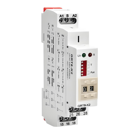
To meet these requirements, a reliable solution is proposed using a time relay as the control core, leveraging its time-delay characteristics and sliding contacts to achieve automatic reclosing. The selected time relay model is DS-28.
The DS-28 time relay used in the device consists of an electromagnet driving a clockwork timing mechanism. The electromagnetic coil draws power from the transformer’s low-voltage output, supplying a continuously energized time relay. The relay contains one set of delayed sliding contacts and one set of delayed main contacts (termination contacts). The internal wiring of the time relay for the undervoltage auto-transfer device is shown in Figure 1.
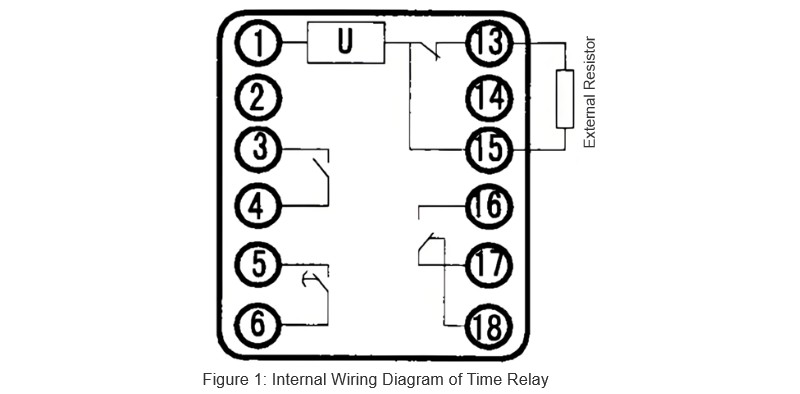
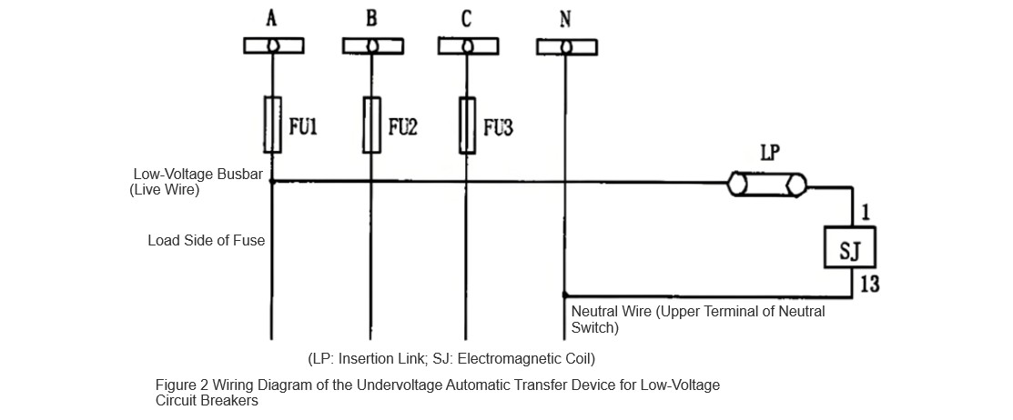
To prevent coil burnout from prolonged energization, a thermal fuse resistor is added as an external protective resistor. In the design, terminals 1 and 13–3 are used as trigger signals connected to the power circuit, while terminals 5 and 6, and 16–3 and 17, serve as the delayed sliding contact and instantaneous normally closed contact, respectively. Figure 2 shows the wiring diagram of the time-relay-based automatic reclosing device for low-voltage circuit breakers.
2.Control Strategy of the Undervoltage Automatic Transfer Device
2.1 Transformer Undervoltage
When the transformer experiences undervoltage, the low-voltage circuit breaker trips. Since the low-voltage bus is not energized, the time relay remains in its initial state, with the delayed sliding contacts and delayed main contacts open, while the instantaneous normally closed contacts are closed.
Upon power restoration to the line, the transformer’s low-voltage output becomes energized, supplying power to the time relay. At this point, the instantaneous normally closed contacts open, introducing a voltage-dividing resistor into the coil circuit, causing the electromagnet to energize and maintain a long-term engagement. The clockwork mechanism begins to operate, and the delayed moving contact starts to move towards the closed position.
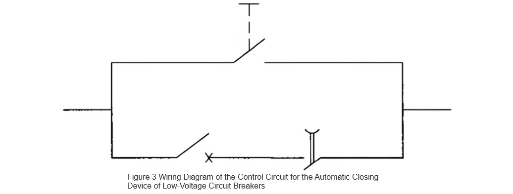
After the preset delay (typically set between 10 to 15 seconds via the time adjustment knob on the time relay panel to avoid transformer inrush current), the delayed sliding contact briefly closes and then opens again. This action simulates pressing and releasing a manual closing button, ensuring that the closing circuit is not continuously energized, which could prevent manual disconnection or cause the circuit breaker to close onto a fault point.
Generally, distribution transformers have capacities up to 2000 kVA, and the duration of transformer inrush current lasts around 6 to 10 seconds. To avoid the impact of transformer inrush current, the delay time is set to 10 to 15 seconds during installation by adjusting the time dial on the time relay panel. The wiring diagram for the closing circuit is shown in Figure 3.
The main (termination) contact closes after the sliding contact and stops at the mechanical stop mechanism. As long as the transformer’s low-voltage output remains energized, the relay will stay in this state. When the low-voltage output loses voltage (i.e., the electromagnetic coil is de-energized), all contacts instantly return to their original positions.
2.2 Circuit Breaker Trip due to Fault
When a fault occurs in the downstream line or equipment of the low-voltage circuit breaker, the breaker trips due to overcurrent. Since the transformer’s low-voltage output remains energized, the relay contacts stay in their current positions, ensuring the circuit breaker does not automatically reclose.
2.3 Manual Trip
When the low-voltage circuit breaker is manually opened, the transformer’s low-voltage output is still energized. The relay contacts remain unchanged, and the closing circuit is unaffected by the time relay, preventing automatic closure of the breaker.
3. Device Function Testing
After assembling the time-relay-based undervoltage automatic transfer device, comprehensive functional tests were conducted. Following successful testing, a standardized installation procedure and wiring diagrams were established, accompanied by detailed safety and technical measures. The device was installed in 10 regions. After six months of operation, the device reliably and correctly operated during both scheduled maintenance outages and fault-induced outages. The average power restoration time decreased from 33 minutes before installation to 10–15 seconds.
Field test results confirm that the time-relay-based undervoltage automatic transfer device for low-voltage circuit breakers meets all design requirements.
4. Conclusion
The proposed undervoltage automatic transfer device for low-voltage circuit breakers utilizes the time relay’s delayed sliding contact to address a series of issues caused by installing undervoltage release coils. It enables low-voltage circuit breakers to achieve automatic reclosing after undervoltage events. The device operates reliably during normal power interruptions and remains inactive during abnormal conditions. With a simple principle, convenient wiring, and low cost, the device has proven in field tests to safely and reliably restore power after undervoltage trips, reducing the circuit breaker closing time from 33 minutes to 10–15 seconds. This significantly improves utility efficiency and power supply reliability, demonstrating high practical value in real-world applications.


