Thermal Relays for Motor Overload Protection: Principles, Selection, and Application
In motor control systems, fuses are primarily used for short-circuit protection. However, they cannot protect against overheating caused by prolonged overloading, frequent forward-reverse operation, or undervoltage operation. Currently, thermal relays are widely used for motor overload protection. A thermal relay is a protective device that operates based on the thermal effect of electric current, and is essentially a type of current relay. It works by generating heat through current flowing in its heating element, causing a bimetallic strip (made of two metals with different expansion coefficients) to deform. When the deformation reaches a certain threshold, it actuates a linkage mechanism, opening the control circuit. This de-energizes the contactor and disconnects the main circuit, thereby protecting the motor from overload.
Thermal relays are classified by the number of heating elements: two-pole and three-pole types. Three-pole relays are further divided into models with and without phase-loss protection. Common series include JR0, JR9, JR14, and JR16. The time-current characteristic (ampere-second characteristic) of thermal relays typically exhibits an inverse-time behavior that matches the motor’s allowable overload curve: the greater the overload current, the shorter the tripping time; conversely, the smaller the overload current, the longer the tripping time. With proper selection, the relay can trip before the motor reaches its thermal limit, thus fully utilizing the motor’s overload capacity while preventing damage.
Due to their small size, simple structure, and low cost, thermal relays are extensively used in industrial applications for motor protection.
I. Protection of Motors by Thermal Relays
The stator winding connection type of a motor determines the overload and phase-loss current characteristics, which in turn dictate the appropriate type of thermal relay.
Star (Y) Connected Stator Windings
In star connection, line current equals phase current. During motor overload, all three phase currents typically increase. When the three-phase supply voltage is balanced and the motor currents are symmetrical, a two-pole thermal relay can effectively protect a three-phase motor. However, if the three-phase voltage is severely unbalanced (e.g., 4% voltage imbalance can cause up to 25% current imbalance), or if a single-phase short circuit occurs where the fault current does not pass through the heating element, the two-pole relay may fail to provide adequate protection. In such cases, a three-pole thermal relay should be used.
Delta (Δ) Connected Stator Windings
Under normal operation, line current (I) = 0.58 × phase current (Iφ), and phase current Iφ = 0.58 × line current I. When one supply phase is lost (e.g., one fuse blows), as shown in Figure 1 (with phase B open), due to equal winding impedance, Ic = Ia + Ib = 1.5Iφ, and Ib = (2/3)Ic. This shows that line current no longer accurately reflects phase current, so using line current for protection fails to detect true winding overload.
When phase loss occurs under full load, Ia = 0.58Ie, Ib = 1.16Ie—this overcurrent is sufficient for a standard three-pole thermal relay to trip. However, under 64% of rated load with phase loss, Ia = 0.37Ie, Ib = 0.75Ie. The overcurrent due to phase loss is less than 20%, so a standard three-pole relay may not trip, yet one phase carries 58% more than its normal current, risking motor burnout. Therefore, for delta-connected motors, standard three-pole thermal relays cannot provide effective protection; phase-loss protective relays must be used.
When one stator winding breaks (e.g., a loose connection between winding lead and terminal, such as open between A and B, as shown in Figure 2), then Ia = Ic = Iφ, and Ib = Iφ. Here, one line current equals phase current, just as in normal operation. In this case, a phase-loss protective relay can still provide protection, whereas phase-loss protection devices that rely on detecting supply-side phase loss will fail to operate.
II. Selection of Thermal Relays
Choosing and using thermal relays properly is a well-known topic, yet motor burnout accidents due to improper selection and use still occur frequently. Therefore, beginners should note the following points in addition to following standard guidelines:
Understand the model, specifications, and characteristics of the motor to be protected.
Type Selection: In rural areas with frequent three-phase voltage imbalance, use standard three-pole thermal relays for star-connected motors, and phase-loss protective relays for delta-connected motors.
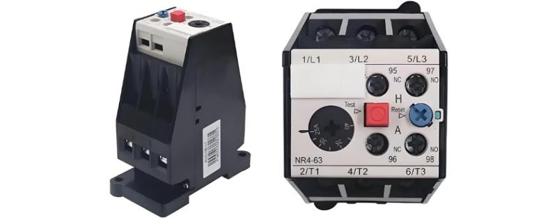
Current Rating Selection: Select the thermal relay’s rated current based on the motor’s rated current, then choose the heating element’s rated current. The adjustable range of the heating element’s setting current can be found in manufacturer tables. If the motor starting current is about 6 times the rated current and starting time is under 5 seconds, set the heating element’s current to equal the motor’s rated current. For motors with longer starting times, impact loads, or where shutdown is not allowed, set the current to 1.1–1.15 times the motor’s rated current.
Example: A motor has a rated current of 30.3 A, starting current 6 times rated, short starting time, and no impact load. Suitable models include JR0-40, JR0-60, or JR16-60. Using JR16-60: relay rated current is 60 A, three-pole type. Select a 32 A heating element, adjustable to around 30.3 A.
Connection Wire Selection: Using wires that are too thick or too thin affects heat dissipation and thus the thermal relay’s performance. Wire size should follow manufacturer instructions or electrical handbooks.
Motors with poor overload capacity or poor cooling: Set the thermal relay’s rated current to 60%–80% of the motor’s rated current.
Reset Mode: Thermal relays typically offer both manual and automatic reset modes, switchable via an adjustment screw. Manufacturers usually ship them in automatic reset mode. The choice depends on the control circuit. As a rule, even if the relay resets automatically, the protected motor should not restart automatically—otherwise, set the relay to manual reset to prevent repeated starts under fault conditions and equipment damage. For example, in manual start/stop circuits using push buttons, automatic reset is acceptable; in automatic start circuits, use manual reset.
III. Precautions During Use
To extend the service life of thermal relays and ensure optimal performance, observe the following:
Use connection wires at the relay terminals with cross-sections strictly according to specifications.
Thermal relays cannot provide short-circuit protection—fuses must be installed separately. They are unsuitable for motors with very long starting times, frequent operation, or intermittent duty cycles.
When installed with other devices, mount the thermal relay below them to avoid heat interference. Clean dust and dirt regularly.
After tripping, automatic reset occurs within 5 seconds; manual reset requires waiting 2 minutes before pressing the reset button.
After a short-circuit fault, check the heating element for damage and the bimetallic strip for deformation (never bend the bimetallic strip), but do not remove components.
When replacing a thermal relay, ensure the new one matches the original specifications.
Conclusion
Only by properly selecting, correctly wiring, and appropriately using thermal relays can effective overload protection for motors be achieved.


