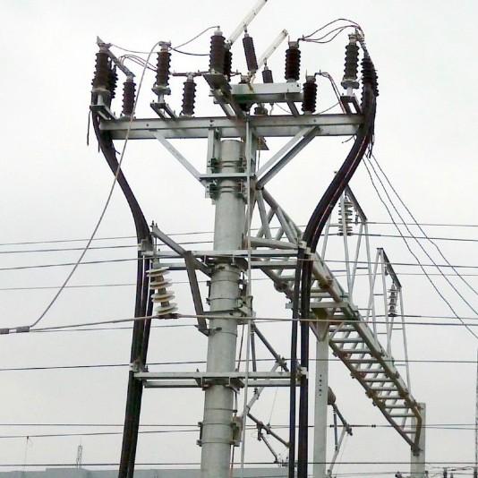
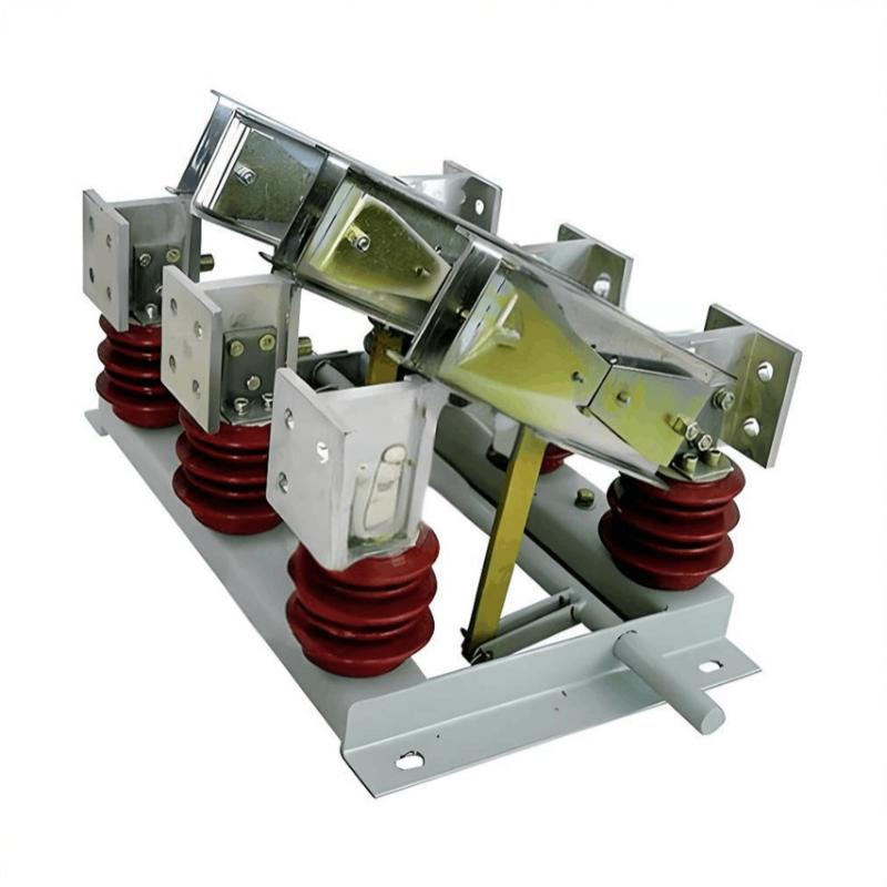
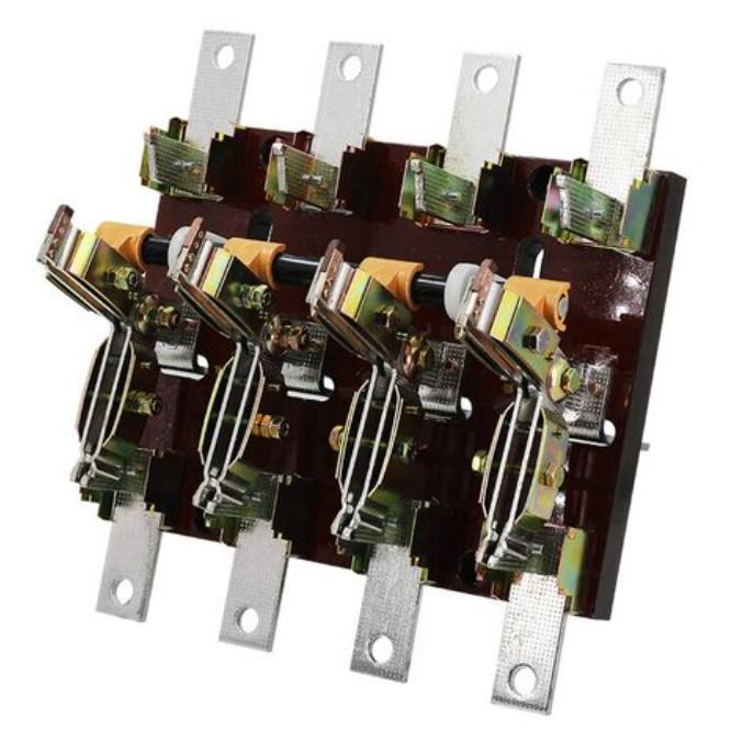
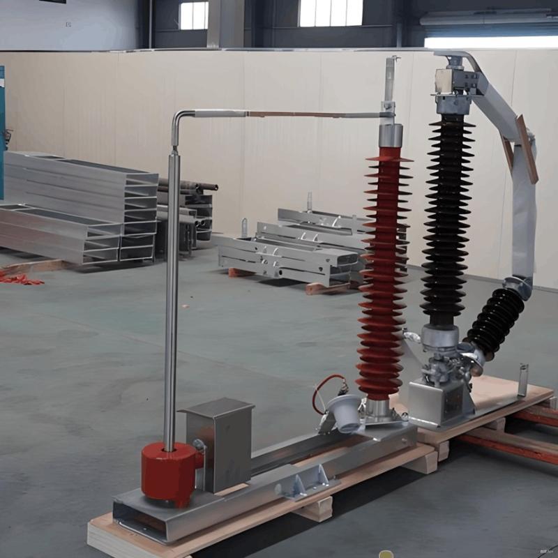
When performing switching operations, operating personnel must carefully verify that the circuit breaker is indeed in the open position. For three-pole interlocked isolating switches, all three phases must move simultaneously, with a maximum allowable vertical discrepancy of no more than 3 mm, before any opening or closing operation of the isolating switch is permitted.
1. Key Points for Closing an Isolating Switch
For manual operation, operating personnel should first remove the interlock pin before proceeding with the closing operation. The initial movement should be slow; as the moving contact approaches the stationary contact, the operation should be completed quickly to prevent arc formation. If an arc appears at the very beginning of closing, the isolating switch must be immediately and fully closed—under no circumstances should the operator attempt to pull it back, as this would enlarge the arc and cause further equipment damage. At the end of the closing stroke, excessive force must be avoided to prevent over-insertion and potential damage to the support porcelain insulator. After closing, operators must carefully inspect whether the contacts are properly engaged—ensuring the moving contact has fully entered the stationary contact—to avoid poor contact leading to overheating.
(1) For rotary-type isolating switches (e.g., those rotating about a shaft), after closing, the blade should lie vertically on the plane of the fixed contact to ensure adequate contact pressure and proper contact resistance.
(2) For horizontally rotating types such as the GW5 isolating switch, the blade should reach a horizontal position upon closing, with its arm fully extended. If the movable cap of the stationary contact shifts to the right, it indicates the moving arm has overshot its correct position.
During winter outdoor operations, ice or frost on contacts can be removed by performing several rapid open-close cycles to generate friction, ensuring good contact after closing. Reliable operation of an isolating switch depends on proper adjustment of its transmission mechanism—if equipped—or on correct use of an insulated operating rod if manually operated.
All isolating switches, regardless of rating, must not automatically disengage under short-circuit conditions. Therefore, when closed, they must be secured by a "Five-Prevention" interlock device. Operators must check this device after each closing operation, insert the locking pin, and engage the interlock to prevent accidental opening and potential accidents.
In summary: When manually closing an isolating switch, act swiftly and decisively—but avoid excessive force near the end of travel to prevent damage to support insulators. If an arc appears or if the switch was mistakenly closed, do not reopen it, as this could result in load-breaking—a serious misoperation that may escalate the incident.
2. Key Points for Opening an Isolating Switch
When opening, begin slowly and cautiously. If an arc occurs as the moving contact separates from the stationary contact, immediately reclose the switch and halt the operation. However, when interrupting small load currents or charging currents, arcs are expected; in such cases, the switch should be opened rapidly to extinguish the arc effectively. Near the end of the opening stroke, slow down to minimize mechanical shock to the support insulator and operating mechanism.
Finally, verify that the interlock pin is properly engaged. After opening, confirm the switch is fully open: the air insulation gap must meet specifications, the moving contact must be fully retracted, and the opening angle must comply with the manufacturer’s requirements. For indoor isolating switches, if the open insulation distance is insufficient, an insulating barrier must be inserted; otherwise, flashover and short-circuit may occur between the energized side and the grounded de-energized side.
In summary: When manually opening an isolating switch, proceed slowly and cautiously. If an arc appears just as contacts separate, immediately reclose and stop—then investigate whether the arc resulted from a misoperation. Before operating, personnel should assess whether arcing is likely. If arcing is expected, the operation must be performed quickly and decisively to extinguish the arc promptly and prevent contact damage.
3. Operating Procedure When Electromagnetic Interlock Fails
Strictly follow the official unlocking procedures for anti-misoperation interlock devices. Carefully verify the actual position of the equipment and obtain explicit authorization from the on-duty dispatcher before disabling the interlock for operation. Most modern substations equip isolating switches with earthing switches for grounding during maintenance of lines, circuit breakers, or isolators. A mechanical interlock is installed between the main isolating switch and its associated earthing switch: when the main switch is closed, the earthing switch cannot be closed; conversely, when the earthing switch is closed, the main switch cannot be closed. This widely adopted interlock prevents accidental grounding.
4. Procedure When Electric Operation Fails
If the electrically operated isolating switch fails to respond, operating personnel must immediately investigate and confirm the actual positions of all associated circuit breakers, isolating switches, and earthing switches that are interlocked with it. Only after verifying that all positions are correct and safe should the operator disconnect the motor power supply and proceed with manual operation.


