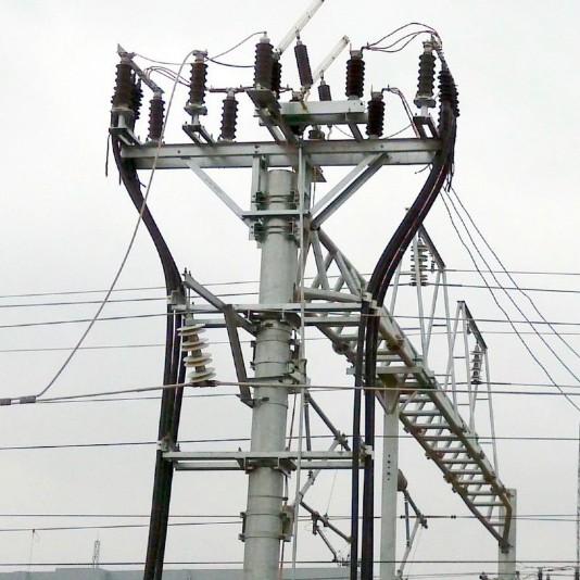
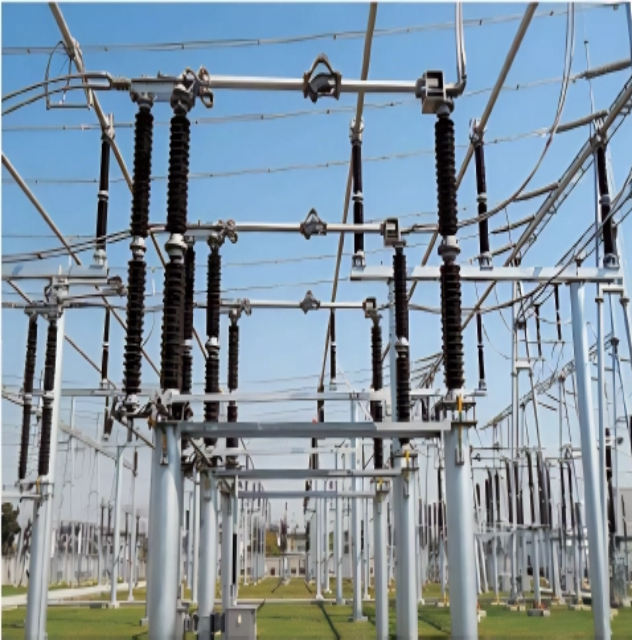
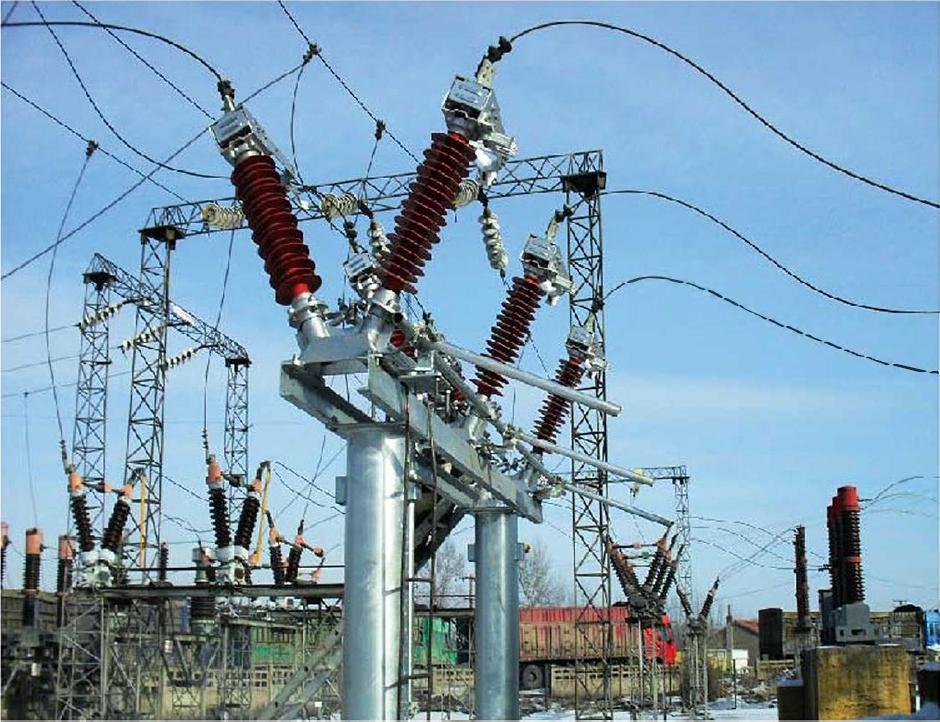
Precautions for Installing Four-Pole Isolating Switches

Installation Requirements for Isolating Switches
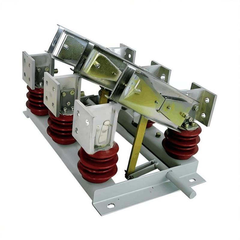
Before installing an isolating switch, a thorough visual inspection must be carried out. The main items to check include:
(1) Verify that the model and specifications of the isolating switch match the design requirements.
(2) Inspect all components for damage and check whether the blade or contacts are deformed. If deformation is found, it should be corrected.
(3) Examine the contact condition between the movable blade and the contacts. Any copper oxide on the contacts or blades must be cleaned off.
(4) Measure the insulation resistance using a 1000 V or 2500 V megohmmeter. The measured insulation resistance must meet the specified requirements.
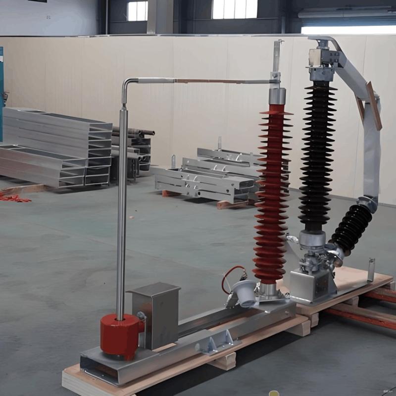
After the main body of the isolating switch, its operating mechanism, and the operating rod are fully assembled, careful adjustment is required to ensure that:
The operating handle reaches its correct position,
The moving blade and contacts also reach their proper positions,
For three-pole isolating switches, all three poles must operate synchronously—i.e., they must close and open simultaneously.
When the isolating switch is in the open position, the opening angle of the blades must comply with the manufacturer's specifications to ensure adequate insulation strength across the open gap.
If the isolating switch is equipped with auxiliary contacts, their operation must also function correctly.
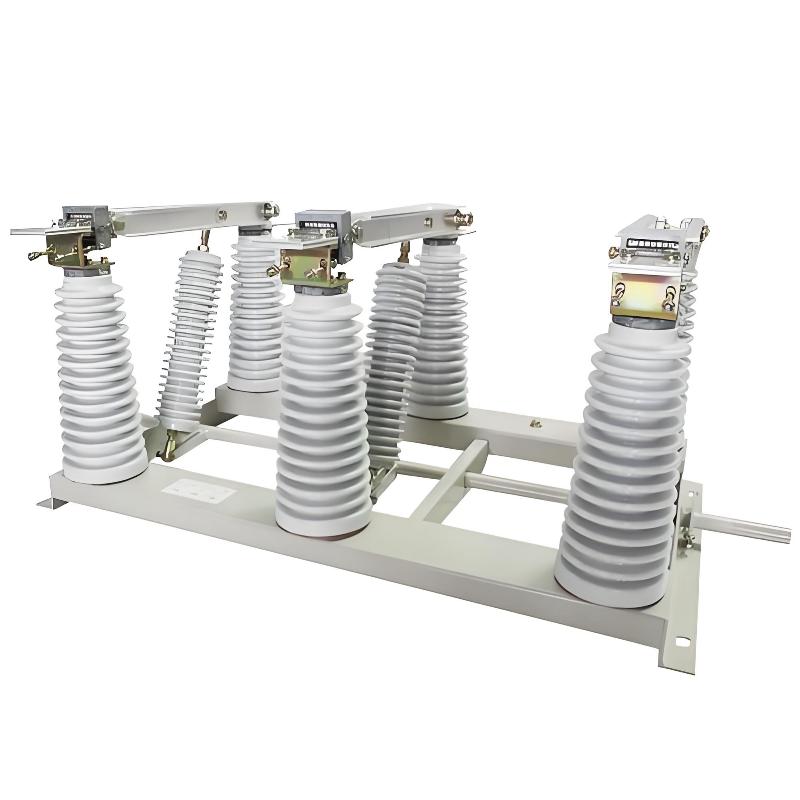
Precautions for Installing Four-Pole Isolating Switches
The following points must be considered when installing four-pole isolating switches:
① Four-pole isolating switches must not be used in TN-C earthing systems.
Although using a four-pole switch to disconnect the neutral conductor could enhance electrical safety during maintenance, the PEN conductor in a TN-C system includes the protective earth (PE) function. Since the PE conductor must never be interrupted, four-pole switches are prohibited in TN-C systems.
② Four-pole isolating switches are generally unnecessary in TN-C-S and TN-S earthing systems.
Both IEC standards and Chinese electrical codes require the implementation of a main equipotential bonding system within buildings. Even in older buildings without formal main equipotential bonding, natural metallic connections (e.g., through structural steel or piping) often provide a certain degree of equipotential bonding. Due to this effect, four-pole switches are not required in TN-C-S or TN-S systems solely for maintenance safety.
③ A four-pole isolating switch must be installed at the incoming point of the low-voltage distribution board in TT earthing systems.
In TT systems, even if a main equipotential bonding system is present within the building, a four-pole switch is still required for maintenance safety. This is because, in TT systems, the neutral conductor is not connected to the equipotential bonding network. Consequently, the neutral conductor may carry a certain voltage—denoted as Ub (as shown in Figure 1).
When the TT system power supply is connected to the low-voltage distribution board, the enclosure of the board is bonded to the main equipotential system, which is at earth potential (0 V). Therefore, a potential difference may exist between the neutral conductor and the equipment enclosure, necessitating disconnection of the neutral during maintenance—hence the requirement for a four-pole isolating switch.
 conductor in a TT system.jpg")
Let’s refer to Figure 2. When a single-phase ground fault occurs in a TT system, the fault current Id flows through the transformer neutral grounding electrode resistance Rb, generating a relatively high voltage Ub across Rb. This causes the voltage on the neutral (N) conductor to rise, potentially posing an electric shock hazard to personnel.
 conductor in a TT system..jpg")
Therefore, in TT systems, a four-pole switch should be installed at the incoming power supply point of the low-voltage distribution board—specifically, the circuit breaker QF shown in Figures 1 and 2 should be a four-pole withdrawable circuit breaker, or a four-pole isolating switch should be installed upstream of the circuit breaker.