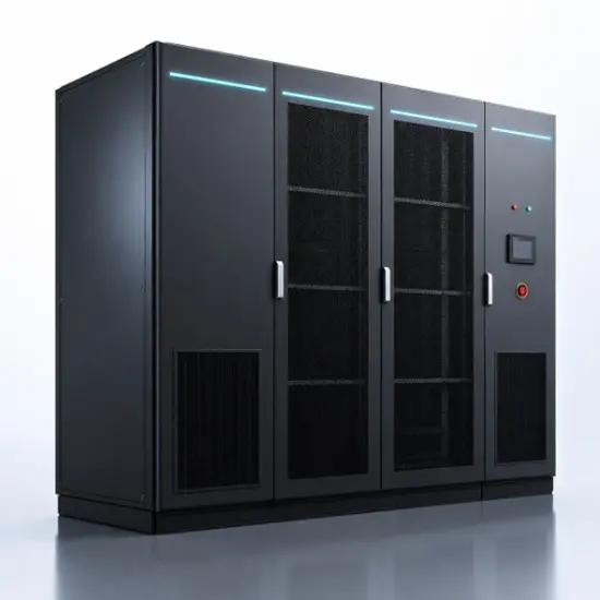
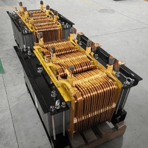
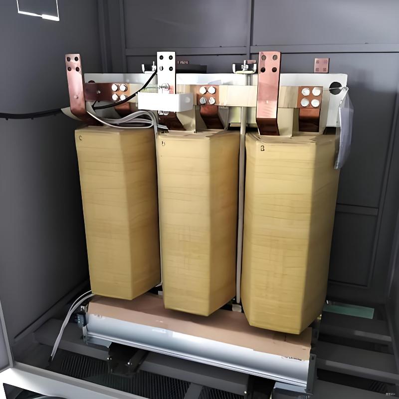
When SiC chips and high-frequency magnetic cores replace silicon steel sheets and insulating oil, the power transformer undergoes its most fundamental physical reconstruction since Faraday's era — from a passive iron core to an intelligent power router, SST redefines the boundary of power conversion at the microsecond scale.
Since its inception in the late 19th century, the fundamental operating principle of the power transformer — electromagnetic induction and magnetic flux linkage through an iron core — has remained essentially unchanged. Iron cores, windings, and insulating oil form the physical DNA of the conventional transformer, a system that has underpinned the global power grid for over a century. However, driven by the dual forces of carbon neutrality targets and digital transformation, the power system is undergoing a profound transition from "rigid interconnection" to "flexible interconnection." The inherent limitations of conventional transformers — bulky volume, passive operation, lack of controllability, and environmental concerns associated with mineral oil — are becoming increasingly pronounced in the context of modern power systems.
The Solid State Transformer (SST) represents a fundamental challenge to this century-old paradigm. By replacing silicon steel sheets with wide-bandgap (WBG) power semiconductor devices, line-frequency iron cores with high-frequency magnetic components, and passive operation with digital control, SST achieves a qualitative leap from "physical rigid voltage transformation" to "intelligent power routing." In March 2026, China's Ministry of Industry and Information Technology, together with three other government departments, jointly issued the Implementation Plan for High-Quality Development of Energy-Saving Equipment (2026–2028), designating the solid state transformer as a priority for promotion — a clear signal that this technology is officially moving from the laboratory into the frontier of industrialization.
This article systematically examines the technical core, topological evolution, and multi-domain application scenarios of solid state transformers, providing power industry professionals with a clear panoramic view of this frontier technology.
2. Technical Core: WBG Devices Driving a Paradigm Reconstruction
2.1 From Silicon to SiC and GaN: A Materials Revolution
The physical foundation of SST's disruption over conventional transformers lies in replacing electromagnetic coupling with power electronic converters. And the key enabler that has moved SST from concept to feasibility is the maturation of wide-bandgap semiconductor materials.
Compared to traditional silicon devices, silicon carbide (SiC) and gallium nitride (GaN) offer three generational advantages:
- Bandgap Width: SiC (3.26 eV) and GaN (3.4 eV) have approximately three times the bandgap of Si (1.12 eV), with critical breakdown field strength elevated by an order of magnitude, enabling safe device operation at higher voltage levels.
- Switching Frequency: SiC MOSFETs can operate efficiently in the range of tens to hundreds of kilohertz — far exceeding the typical kilohertz-level switching of silicon IGBTs — directly enabling the miniaturization of high-frequency transformers.
- Conduction and Switching Losses: SiC devices feature low on-resistance and near-zero reverse recovery charge, achieving over 50% reduction in combined losses compared to silicon-based solutions in medium- and high-voltage applications.
In March 2026, domestic enterprises achieved high-yield mass production of ultra-high-voltage SiC chips, laying the device foundation for the large-scale deployment of SSTs in medium-voltage distribution networks (10 kV to 35 kV).
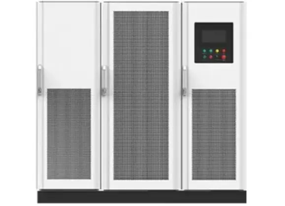
2.2 High-Frequency Magnetic Components: Redefining the Physical Form of Transformers
The volume and weight of conventional line-frequency transformers are primarily determined by core dimensions, which are inversely proportional to operating frequency. When the switching frequency increases from 50 Hz to the 20 kHz–100 kHz range, the theoretical volume of magnetic components can be reduced to a fraction of the original — down to several hundredths.
However, high-frequency operation also introduces new engineering challenges:
- Core Material Selection: Amorphous and nanocrystalline materials, which combine high saturation flux density with low loss characteristics at high frequencies, have become the preferred core solution for SST high-frequency transformers. Companies such as Click have successfully developed high-frequency transformer product lines for 10 kV grid-connected SSTs, covering switching frequencies from 20 kHz to 100 kHz.
- Insulation and Thermal Management: High-frequency square-wave voltages impose severe stress on inter-turn insulation, significantly increasing the risk of partial discharge. The insulation design of medium-voltage high-frequency transformers has become a key research focus for international bodies such as IEEE and CIGRE.
- Electromagnetic Compatibility (EMC): The high dv/dt switching waveforms of SiC devices generate broadband electromagnetic interference, placing far more demanding requirements on filtering and shielding design than those for conventional transformers.
3. Topology Evolution: The Efficiency Race from Three-Stage to Single-Stage
3.1 The Classical Three-Stage Architecture
The classical SST topology follows a three-stage structure: AC-DC rectification stage + isolated DC-DC conversion stage + DC-AC inversion stage. This architecture offers clear functional separation and allows independent optimization at each stage, making it the mainstream solution for commercially available SSTs.
Representative 10 kV / 2.4 MW class SST prototypes — employing all-SiC solutions and cascaded H-bridge structures — have achieved conversion efficiencies of 98%. Domestic enterprises including JST and Shunna have completed design verification and commercial delivery of SST prototypes at this power level.
3.2 Moving Toward Two-Stage and Single-Stage Topologies
The frontier trend in 2026 is the evolution from three-stage to two-stage and ultimately single-stage topologies. The core logic is to reduce power conversion stages by reusing power devices across stages, thereby further improving efficiency and reducing cost.
- Two-Stage: Combining the rectification and isolation stages, with a matrix converter or dual active bridge (DAB) at the core, this approach eliminates the intermediate DC-link electrolytic capacitor — which is precisely the lifetime bottleneck component in conventional power electronic converters.
- Single-Stage: Based on the modular multilevel converter (MMC), this topology achieves single-stage isolated conversion directly from medium-voltage AC to low-voltage DC. Enterprises such as GE Vernova have already validated the feasibility of this approach in high-power scenarios above 10 MW.
The trade-off for topological simplification is a significant increase in control complexity. A single-stage SST must simultaneously perform voltage conversion, galvanic isolation, harmonic suppression, and fault ride-through within a single converter, placing extreme demands on real-time control algorithms and digital signal processors.
3.3 Modularity and Scalability
Regardless of the topology employed, modularity is one of the core advantages that distinguishes SSTs from conventional transformers. Multiple submodules can be configured in input-series output-parallel (ISOP) or input-parallel output-series (IPOS) arrangements, achieving flexible matching of any voltage and power level through cascading. This "power electronics building block" architectural philosophy enables SSTs to inherently possess N+1 redundancy and plug-and-play scalability — attributes well aligned with the flexibility and resilience requirements of modern power systems.
4. Application Scenarios: Multi-Domain Penetration from Data Centers to Modern Power Systems
4.1 AI Computing Centers and Green Data Centers
Data center power supply architectures have undergone three generations of evolution: from conventional AC UPS to high-voltage direct current (HVDC), and now to SST. The exponential growth in AI computing density demands that power supply systems deliver higher power density and higher efficiency within limited physical space.
With conversion efficiencies above 98%, power density three to five times that of conventional transformers, and inherent compatibility with DC distribution architectures, SST is emerging as the power distribution core for next-generation AI data centers. Internet companies such as Kuaishou have explicitly proposed 800 V DC power supply architectures, where SSTs perform direct conversion from 10 kV AC to 800 V DC, eliminating multi-stage cascading losses.
4.2 Modern Power Systems and Distributed Energy Integration
Conventional transformers are designed for unidirectional power flow, whereas distribution networks with high penetration of photovoltaics, energy storage, and EV charging stations impose rigid requirements for bidirectional power regulation. SSTs offer bidirectional power flow capability and millisecond-level independent reactive/active power control, providing voltage support, harmonic mitigation, and islanding detection — among other advanced functions — for distributed generation grid integration, substantively advancing distribution networks from "passive hosting" to "active management."
4.3 Railway Traction and Electrified Transportation
Electrified railway traction power supply systems are highly sensitive to volume and weight. SST's high power density characteristics have demonstrated significant advantages in 25 kV single-phase AC railway applications. Research literature indicates that medium-voltage SSTs can reduce traction transformer weight by over 60% while improving overall efficiency by approximately 3%, aligning with the pressing demands for energy conservation and emission reduction in railway systems.
4.4 Ultra-Fast EV Charging
Ultra-fast charging stations rated at 350 kW and above impose severe impacts on distribution networks. Conventional line-frequency transformer plus rectifier approaches struggle to simultaneously deliver high power density and grid compatibility. SiC-based SST solutions can draw power directly from medium-voltage distribution networks, outputting adjustable DC voltage in a single conversion stage, significantly reducing the equipment footprint and distribution hierarchy of charging stations.
5. Practical Value and Outlook
For electrical engineers, the solid state transformer is not simply a drop-in replacement for the conventional transformer — it represents a technical proposition that demands a systematic shift in thinking:
- Design Philosophy Transformation: Shifting from electromagnetic design-centric approaches to equal emphasis on power electronic topology design and control algorithms. Engineers must bridge the knowledge gap spanning both power systems and power electronics disciplines.
- O&M Paradigm Shift: The digital core of SSTs endows them with intelligent capabilities — self-aware condition monitoring, lifetime prediction, and fault self-diagnosis. The conventional transformer maintenance model of "scheduled overhaul plus failure replacement" will progressively give way to "predictive maintenance."
- Standards System Reconstruction: SST testing standards remain in evolution. While organizations such as EPRI have published white papers on medium-voltage SST applications, mature type-testing and grid-connection verification specifications are still lacking — a critical bottleneck for industrial-scale deployment.
- Cost Curve Decline: SiC device costs have fallen by over 50% over the past five years. With the transition from 6-inch to 8-inch wafer production lines, costs are expected to converge further toward silicon-based solutions. The industry broadly anticipates that SSTs will progressively establish a total cost of ownership (TCO) advantage over conventional transformers.
What the solid state transformer represents is a quiet revolution — from "iron cores and copper windings" to "chips and algorithms." It not only reconstructs the method of power conversion but reshapes how the grid manages power flow. While high-voltage grids are accustomed to enormous inertia, SST redefines our cognitive boundary of "voltage transformation" at the microsecond scale. For electrical engineers standing at the crest of this technological wave, understanding SST is not merely about tracking the frontier — it is about participating in defining the fundamental form of the future power grid.
Quora:
https://qr.ae/pFG9FL

 Login
Login