• Product
  • Suppliers
  • Manufacturers
  • Solutions
  • Free tools
  • Knowledges
  • Experts
  • Communities
Search


What are the advantages of high-voltage single-phase distribution transformers in the distribution network?

Echo
Echo
Field: Transformer Analysis
China

1.1 Voltage Qualification Rate Improvement

High - voltage single - phase distribution transformers overcome traditional low - voltage distribution drawbacks like line losses, boosting power supply reliability.

Low - voltage distribution causes up to 35% voltage drop, disrupting supply. Switching to high - voltage single - phase transformers limits drops to ≤7%, preventing low - voltage issues at user ends. Stable voltage ensures proper appliance operation.

1.2 Power Supply Reliability Enhancement

High - voltage single - phase transformers serve far fewer users than box - type/three - phase ones. Maintenance thus minimally impacts users. In hot seasons, low - voltage setups risk overheating (56% of low - voltage faults stem from this). Smaller - capacity high - voltage single - phase units reduce such risks. Also, they avoid low - voltage line - related problems (theft, unsafe wiring). Using insulated/semi - insulated high - voltage lines enables fully sealed transformers, cutting failure chances. This stabilizes power supply.

1.4 Other Advantages of High - Voltage Single - Phase Distribution Transformer Power Distribution Mode

High - voltage single - phase distribution transformers can eliminate harmonics, thus preventing electricity theft and ensuring power facility safety. They also control no - load current, improve the power - use environment, and reduce noise.

2 Application in Distribution Networks

Proper use of high - voltage single - phase distribution transformers in distribution networks effectively cuts losses.

2.1 Transformer Types

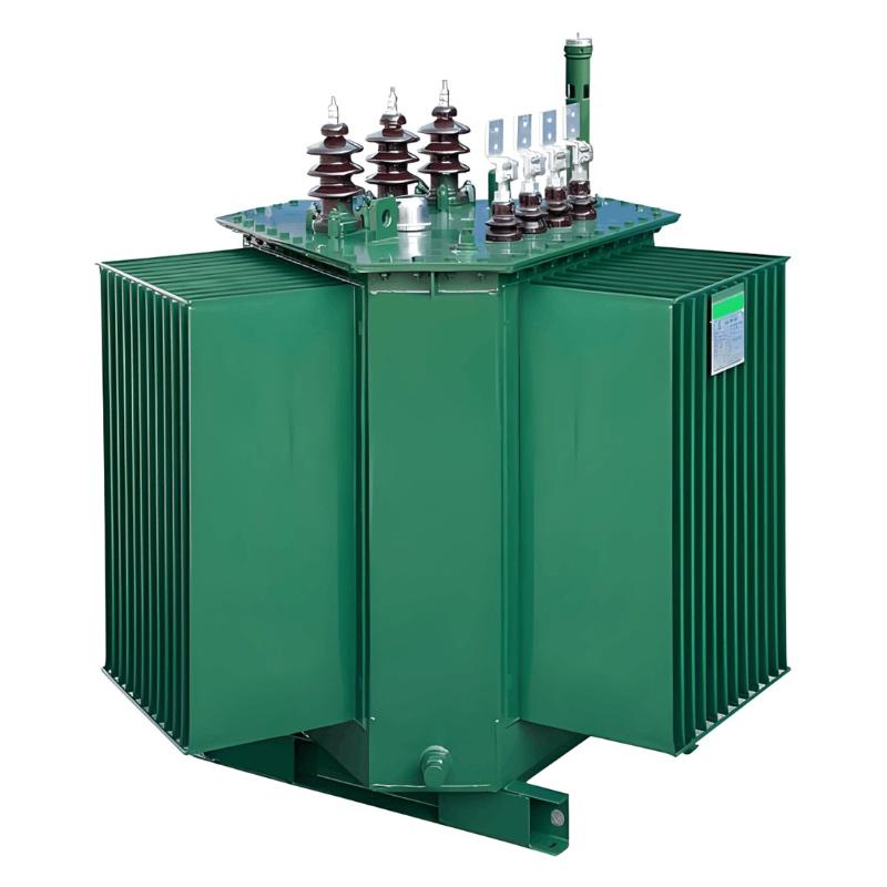
These transformers are mostly three - phase units made of single - phase transformers or pole - mounted single - phase ones. Crafted via cold - rolled silicon steel sheets and wound - core annealing, single - phase Dl2 - type transformers slash iron loss. They deliver 6 kV or 10 kV high voltage directly to users, minimizing line losses.

2.2 Distribution Modes

On the high - voltage side, they connect to the 10 kV system’s AB, BC, CA phases. Two low - voltage connection methods exist:

  • Single - phase three - wire: Windings on both sides; the low - voltage center tap is grounded, keeping the voltage ratio at 0.22 kV/10 kV (see Figure 1).

  • Single - phase two - wire: Windings on both sides; one low - voltage end links to the live wire, the other to ground, with the same 0.22 kV/10 kV ratio (see Figure 2).

2.3 Power Distribution Technology of High - Voltage Single - Phase Distribution Transformers

This technology features:

  • Pole - mounted single - phase transformers distribute power via 220 V low - voltage lines. Minimize incoming line lengths (ideally ≤23 m).

  • Match transformer capacity to peak user demand for small - capacity, dense distribution points.

  • Switching stations/distribution rooms supply power directly via 10 kV lines.

  • Install electric meters centrally in residential buildings, one meter per household.

3 Key Considerations for Applying High-Voltage Single-Phase Distribution Transformers in Distribution Networks

Although the high-voltage single-phase distribution transformer offers unparalleled advantages over low-voltage distribution systems, its full potential cannot be realized without proper control of the power distribution system. Therefore, the following points should be noted during application:

3.1 Managing Load Current in the Distribution System

Due to their relatively small capacity, high-voltage single-phase distribution transformers are easier to adjust when load current fluctuations occur. Operators should regulate current according to users' power consumption to minimize load imbalances. Single-phase transformers are more prone to load current issues, which can be mitigated by integrating three-phase transformers to achieve current balance in 10 kV measurement lines.

3.2 Ensuring Compatibility Between Transformer Capacity and User Equipment

Select transformer capacity that matches the maximum power demand of connected appliances. Proper capacity matching not only meets user needs but also reduces line losses. Three-phase power supply systems are generally sufficient for most user requirements.

3.3 Prioritizing Safety of the Distribution System

Traditional three-phase four-wire systems are susceptible to neutral wire breakage, which can cause sudden voltage spikes on live wires, endangering lighting systems and electrical appliances. In contrast, single-phase distribution systems used in high-voltage single-phase transformers eliminate this risk, ensuring safer operation of user equipment.

Give a tip and encourage the author!
Recommended
3D Wound-Core Transformer: Future of Power Distribution
Technical Requirements and Development Trends for Distribution Transformers Low losses, especially low no-load losses; highlighting energy-saving performance. Low noise, particularly during no-load operation, to meet environmental protection standards. Fully sealed designto prevent transformer oil from contacting external air, enabling maintenance-free operation. Integrated protection devices within the tank, achieving miniaturization; reducing transformer size for easier on-site installation. C
Echo
10/20/2025
Reduce Downtime with Digital MV Circuit Breakers
Reduce Downtime with Digitized Medium-Voltage Switchgear and Circuit Breakers"Downtime" — it’s a word no facility manager wants to hear, especially when it’s unplanned. Now, thanks to next-generation medium-voltage (MV) circuit breakers and switchgear, you can leverage digital solutions to maximize uptime and system reliability.Modern MV switchgear and circuit breakers are equipped with embedded digital sensors that enable product-level equipment monitoring, providing real-time insights into the
Echo
10/18/2025
One Article to Understand the Contact Separation Stages of a Vacuum Circuit Breaker
Vacuum Circuit Breaker Contact Separation Stages: Arc Initiation, Arc Extinction, and OscillationStage 1: Initial Opening (Arc Initiation Phase, 0–3 mm)Modern theory confirms that the initial contact separation phase (0–3 mm) is critical to the interrupting performance of vacuum circuit breakers. At the beginning of contact separation, the arc current always transitions from a constricted mode to a diffused mode—the faster this transition, the better the interruption performance.Three measures c
Echo
10/16/2025
Advantages & Applications of Low-Voltage Vacuum Circuit Breakers
Low-Voltage Vacuum Circuit Breakers: Advantages, Application, and Technical ChallengesDue to their lower voltage rating, low-voltage vacuum circuit breakers have a smaller contact gap compared to medium-voltage types. Under such small gaps, transverse magnetic field (TMF) technology is superior to axial magnetic field (AMF) for interrupting high short-circuit currents. When interrupting large currents, the vacuum arc tends to concentrate into a constricted arc mode, where localized erosion zones
Echo
10/16/2025
Send inquiry
Download
Get the IEE Business Application
Use the IEE-Business app to find equipment, obtain solutions, connect with experts, and participate in industry collaboration anytime, anywhere—fully supporting the development of your power projects and business.