The power which exists in the circuit when the voltage and current are out of phase to each other, such type of power is known as the reactive power. The formula measures the reactive power in the circuit

Reactive Power Measurement & Varmeters
Reactive power measurement is critical as it indicates circuit power loss: low reactive power worsens load power factor, increasing system losses. Varmeters (volt-ampere reactive meters) measure reactive power and are categorized by circuit phases:
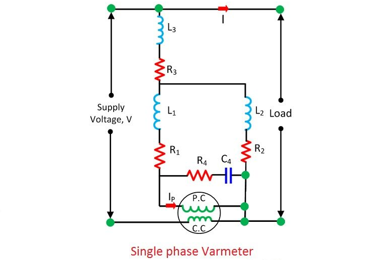
Single Phase Varmeter: A modified electrodynamometer wattmeter with a highly inductive pressure coil (voltage lags current coil by 90°). The current coil carries load current, which has a 90° phase difference from supply voltage.
Polyphase Varmeter: For multi-phase circuits (details not specified here).

The circuit diagram of the single phase varmeter is shown in the figure below.
Single Phase and Polyphase Varmeters
Single Phase Varmeter: Prone to inaccuracies due to harmonics or frequency deviations from calibration conditions, leading to incorrect readings.
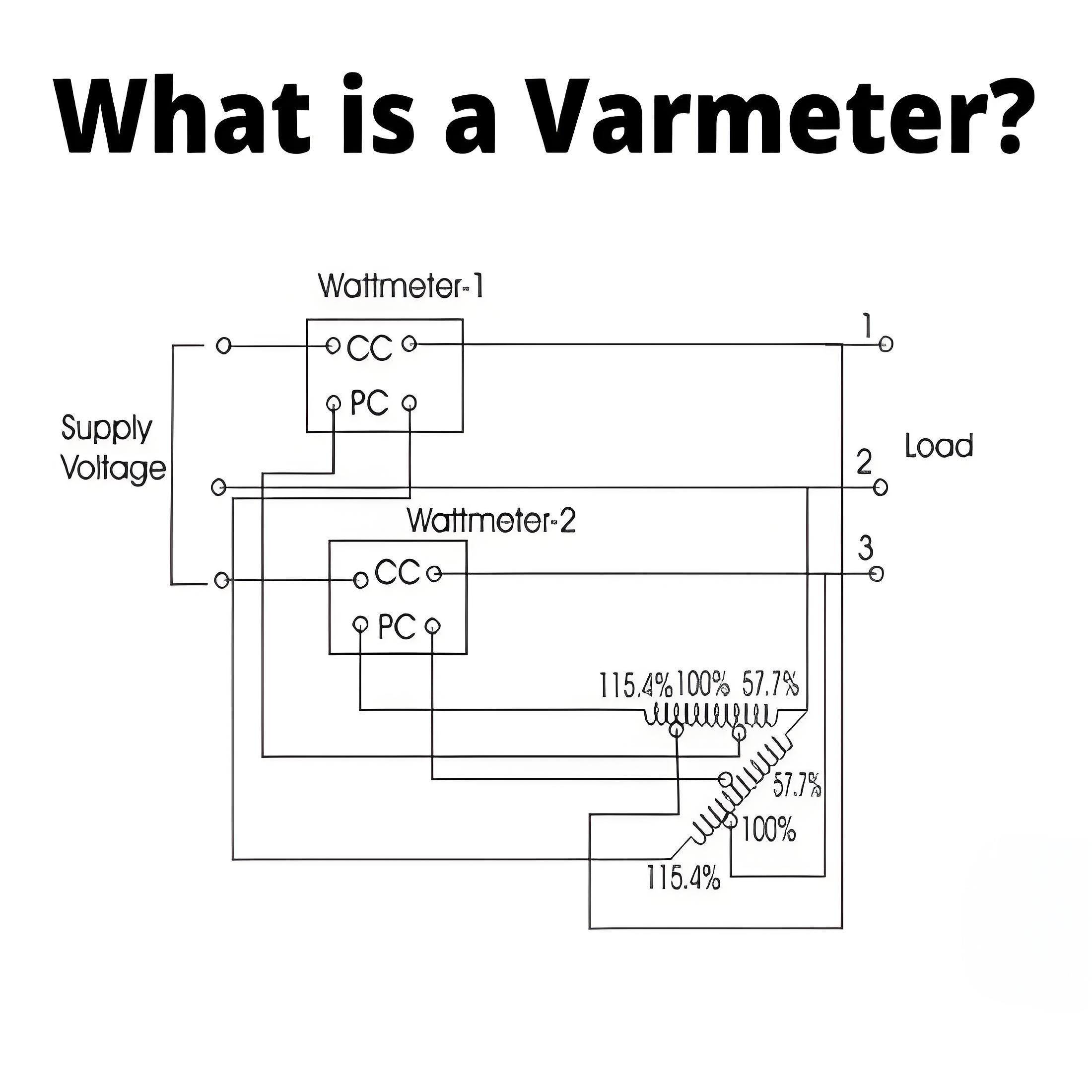
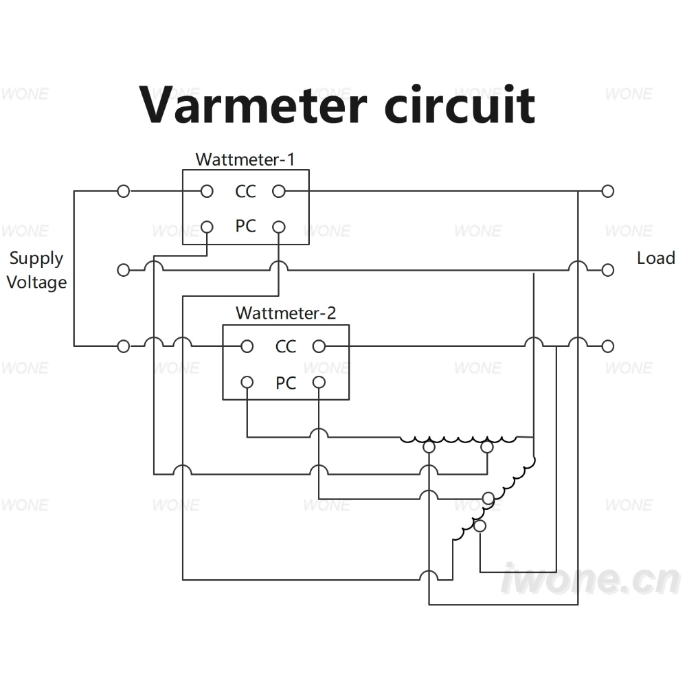
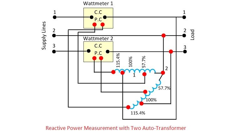
Polyphase Varmeter: Measures reactive power (caused by voltage-current phase displacement) using a phase-shifting transformer (two open-circuit transformers in open delta configuration). Current coils connect in series with the line; pressure coils link to the auto-transformers’ common terminals.
Varmeter Tappings and Three-Phase Reactive Power Measurement
Auto-Transformer Tappings in Varmeters: Auto-transformers have tappings at 57.7%, 100%, and 115.4% (maximum line voltage). One wattmeter’s pressure coil connects to the 115.4% tapping, the other to 57.7%. Both coils produce voltages equal to line voltage but with a 90° phase shift; summing their readings gives total reactive power.
Balanced Three-Phase Circuits: Use the single wattmeter method: current coil in one phase, pressure coil across another phase to measure reactive power.
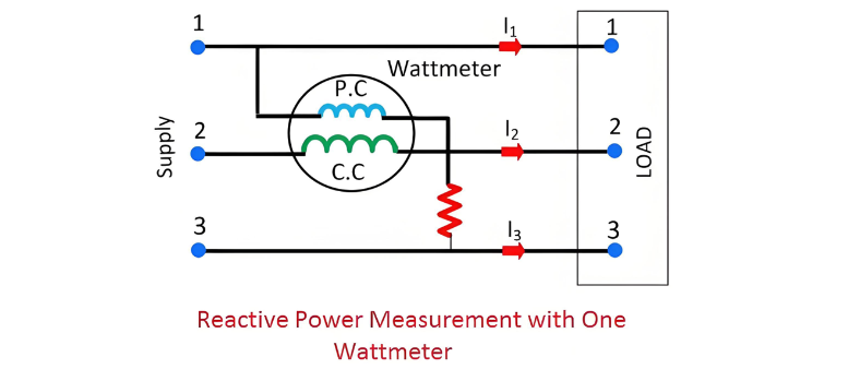
Let the current through the current coil – I2 ,Voltage across the pressure coil – V13

Total reactive volt amperes of the circuit

The phase angle


 Login