• Product
  • Suppliers
  • Manufacturers
  • Solutions
  • Free tools
  • Knowledges
  • Experts
  • Communities
Search


Online GIS PD monitoring system according to IEC61850 protocol

Edwiin
Edwiin
Field: Power switch
China

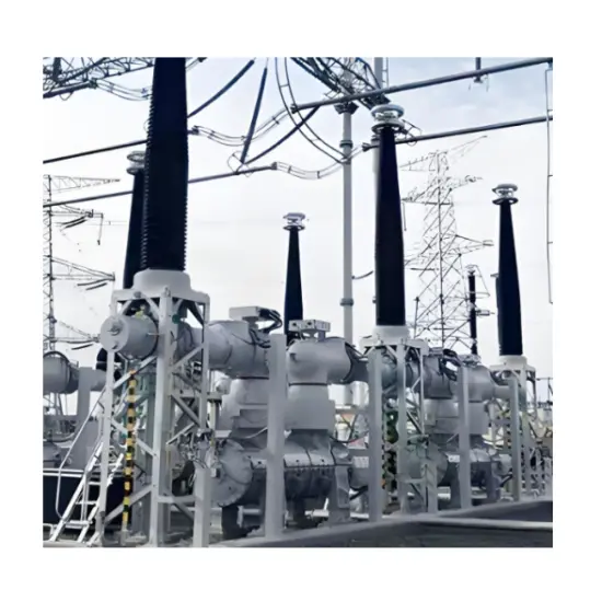
Partial Discharge (PD) Detection in GIS

Both UHF (Ultra-High Frequency) and ultrasonic methods are effective for detecting partial discharges (PD) in Gas-Insulated Switchgear (GIS), each with distinct advantages:

  • UHF Method: Detects PD pulses via high-frequency electromagnetic waves generated by PD activity within GIS.

  • Ultrasonic Method: Identifies ultrasonic waves produced by bubble shocks caused by PD.

Key Monitoring Data

The main data monitored by a GIS PD monitoring system includes:

  • UHF PD signals

  • Ultrasonic PD signals

  • Transformer voltage signals

The online monitoring system collects these signals and generates alarm information based on the GIS’s operational status.

System Composition

A GIS PD monitoring system comprises three core components:

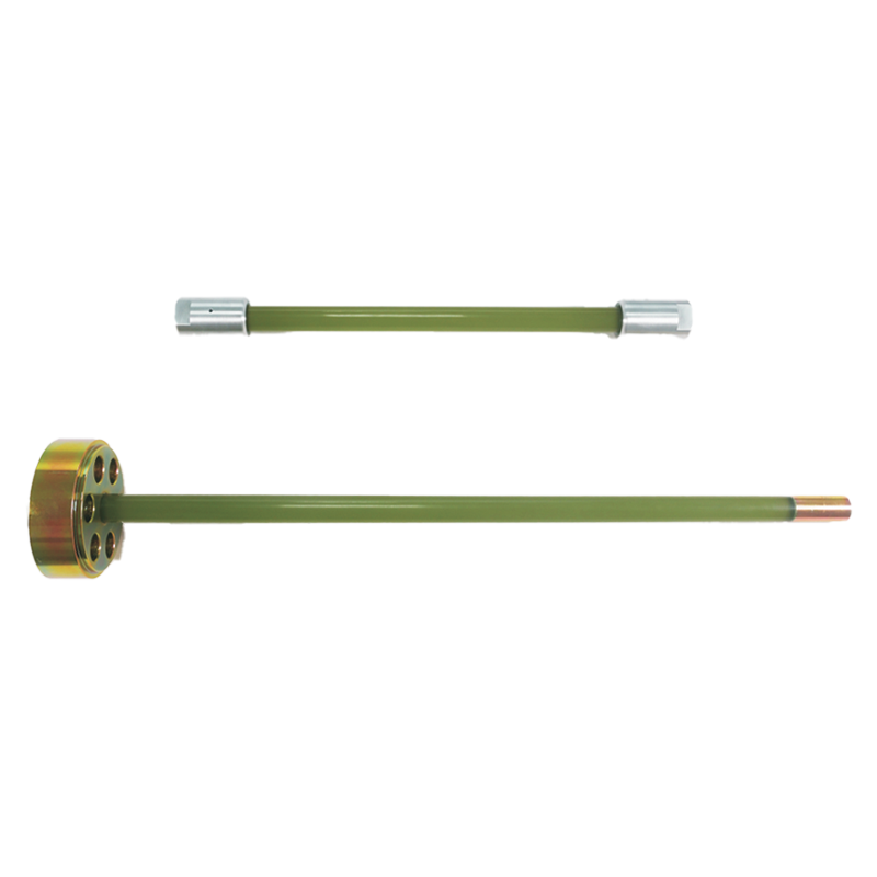
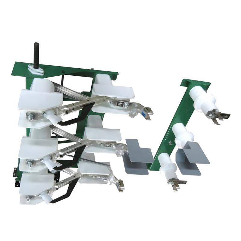
  • Sensors: Capture PD-related signals.

    • UHF PD sensors detect electromagnetic signals.

    • Ultrasonic sensors measure acoustic signals.

  • Data Preprocessing System: Conditions and prepares signals for analysis.

  • PD Monitoring IED (Intelligent Electronic Device): Processes, stores, and displays data at the bay level.

Signal Flow and Communication

  • Process Level: UHF and ultrasonic sensors acquire electrical and acoustic signals, which are conditioned and transmitted to the PD monitoring IED.

  • Bay Level: The IED stores, displays, and processes data. Specific communication service mapping (per IEC 61850) defines network transmission standards for sampled values between the process and bay levels.

  • Station Level: Data is reported from the bay level to the station level via predefined communication services for centralized monitoring.

System Structure

The figure illustrates the architecture of a GIS PD monitoring system compliant with IEC 61850 standards.

Give a tip and encourage the author!
Recommended
 Electrical Room Power-On Safety Operation Guide
Electrical Room Power-On Safety Operation Guide
Power Supply Procedure for Low-Voltage Electrical RoomsI. Pre-Power-On Preparations Clean the electrical room thoroughly; remove all debris from switchgear and transformers, and secure all covers. Inspect busbars and cable connections inside transformers and switchgear; ensure all screws are tightened. Live parts must maintain adequate safety clearance from cabinet enclosures and between phases. Test all safety equipment before energizing; use only calibrated measuring instruments. Prepare fire-
Echo
10/28/2025
Low-Voltage Distribution Cabinet Maintenance Steps and Safety Guide
Maintenance Procedure for Low-Voltage Power Distribution FacilitiesLow-voltage power distr ibution facilities refer to the infrastructure that delivers electrical power from a power supply room to end-user equipment, typically including distribution cabinets, cables, and wiring. To ensure the normal operation of these facilities and guarantee user safety and power supply quality, regular maintenance and servicing are essential. This article provides a detailed introduction to the maintenance pro
Edwiin
10/28/2025
Low-Voltage Electrical Work Safety Preparation and Operation Guide
Low-Voltage Electrician Safety Operating Procedures1. Safety Preparation Before performing any low-voltage electrical work, personnel must wear approved protective equipment, including insulating gloves, insulating boots, and insulating workwear. Carefully inspect all tools and equipment for proper operation. Report any damage or malfunction immediately for repair or replacement. Ensure adequate ventilation at the worksite. Avoid prolonged work in confined spaces to prevent fire hazards or poiso
Echo
10/28/2025
How to Handle Common Faults in RMU and Transformer Substations?
1. Ring Main Unit (RMU) and Transformer SubstationThe ring main unit (RMU) and transformer substation is a critical terminal in a distribution ring network system. The operational status of this terminal is directly affected by the performance of the distribution ring network system. Therefore, this section discusses the advantages, system composition, and key characteristics of the distribution ring network.1.1 Advantages of RMU and Transformer SubstationDue to technological limitations, radial
Felix Spark
10/28/2025
Related Products
Send inquiry
Download
Get the IEE Business Application
Use the IEE-Business app to find equipment, obtain solutions, connect with experts, and participate in industry collaboration anytime, anywhere—fully supporting the development of your power projects and business.