Operational Analysis and Maintenance Strategies for High-Voltage Disconnect Switches in Power Systems

I. Operational Analysis
1.1 Operating Scope
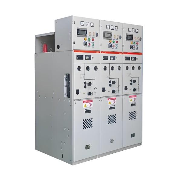
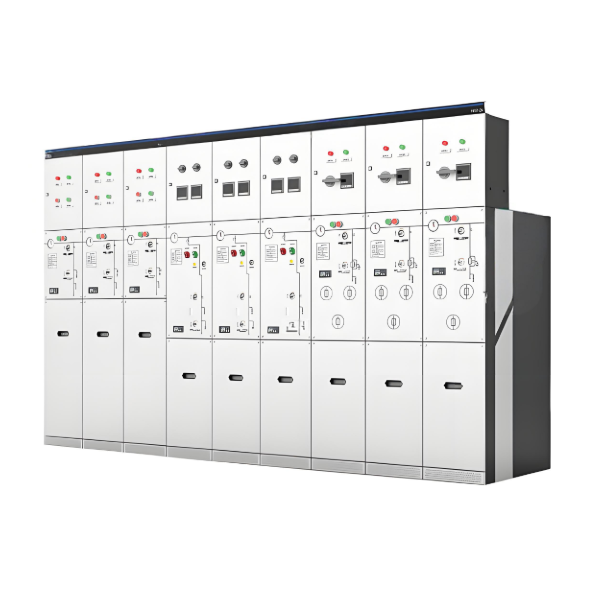
High-voltage disconnect switches are classified into outdoor and indoor types based on installation location, and into three-pole or single-pole configurations according to the number of poles. During operation, attention must be closely paid to the switch’s operating current and voltage.
If the operating voltage exceeds the rated value, discharge may occur within the porcelain insulator. The degree of heating is closely related to the operating current and has a significant impact on whether the external structure deforms. Field operating regulations require that the operating temperature of disconnect switches be controlled within 70°C. Since dedicated arc-extinguishing devices are not installed, the application of disconnect switches is inherently limited. However, they may be used in the following scenarios:
Connecting or disconnecting fault-free lightning arresters and voltage transformers
Connecting or disconnecting busbar currents at 220kV or below, with approval from the equipment management department;
Opening or closing the neutral grounding switch of a fault-free transformer;
Opening or closing unloaded lead wires with current below 5A, and controlling magnetizing current during switching operations below 2A for unloaded transformers;
Opening or closing busbar loop currents, subject to approval by the equipment management authority;
Opening or closing equipotential loop currents at 220kV or below. However, measures must be implemented to prevent accidental tripping of circuit breakers within the loop.
1.2 Precautions During Operation
Never operate the isolator under load (i.e., do not energize while switching);
Prevent closing the grounding switch into a live circuit;
Strictly prohibit switching fault currents or operating under load conditions.
If a disconnect switch is mistakenly operated under load, the operator must immediately reverse the action direction to extinguish the arc promptly and prevent further arcing. Before operating a disconnect switch, ensure that the associated circuit breaker control power is engaged. Only after the circuit breaker is open, the grounding switch is disconnected, grounding wires removed, and the breaker is in the open position, can switching operations be performed.
During energizing, close the busbar-side isolator first, then the load-side isolator. During de-energizing, reverse the sequence. To ensure personnel safety, remote operation is preferred. If remote electric control fails, local electric operation should be performed. When both fail, manual operation may be conducted only after following the unlocking procedure and obtaining proper authorization.
During operation, monitor the sound of the traditional mechanism for abnormalities and confirm whether the full stroke is completed. Additionally, pay close attention to whether all three phases operate synchronously and accurately verify their final positions.
When manually operating a disconnect switch, wear insulated gloves. In rainy weather, use insulated rods with rain shields and wear insulated boots. Manual operation should be swift, but excessive impact should be avoided near the end of the stroke. After closing, inspect the contact surface for integrity. When manually opening, rapidly accelerate arc extinction once the blade separates from the contact. After opening, check the separation angle to ensure it meets specifications.
II. Maintenance Strategies
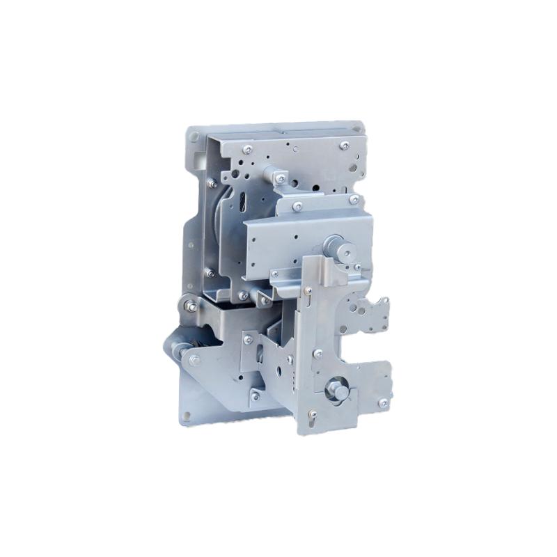
A disconnect switch primarily consists of the following components: transmission mechanism, insulation section, support base, operating mechanism, and conductive parts. The operating mechanisms are categorized into power-driven and manual types. Power-driven mechanisms include pneumatic, hydraulic, and electric types. Maintenance of disconnect switches should address both primary and secondary systems. Specific maintenance procedures are as follows:
2.1 Primary System Maintenance
First, inspect the external appearance:
Check whether the knife switch joints make tight and good contact;
Assess for severe burning or bending;
After opening the switch, use a telescope to observe contacts for oxidation, discoloration, deformation, or burn marks;
Check if porcelain insulators are clean and free from cracking, corona discharge, or audible discharges;
Inspect flange grounding for cracks;
Examine screws for rust or looseness;
Verify proper positioning of the grounding switch;
Confirm secure connection of grounding down conductors;
Ensure mechanical interlocks are intact;
Check transmission mechanisms for bending;
Inspect components for rust, loosening, or detachment.
Lubricate the transmission mechanism regularly and apply industrial-grade grease to friction points periodically.
Second, closely monitor operating current and voltage. During peak load periods, measure temperature to ensure it remains within acceptable limits.
Third, perform special inspections under abnormal conditions:
In extreme weather such as typhoons, check for loose connections, broken strands, poor contact, or strand scattering at terminal joints;
Look for foreign objects on the switch;
In rainy or foggy conditions, inspect porcelain insulators for flashover, discharge, or corona;
After a fault trip, check the switch position and look for signs of overheating at contacts, component deformation, or overheated terminal joints.
2.2 Secondary System Maintenance
When maintaining the secondary system:
First, verify the correctness of secondary wiring diagrams and confirm compliance with design requirements. Check for missing components, design flaws, or unimplemented local modifications. Assess whether motor protection and interlocking functions are necessary.
Second, conduct an on-site verification against the drawings. Record and report any discrepancies. These two steps are fundamental and critical.
Third, perform maintenance per standards:
Confirm that the "five-prevention" (5P) interlock system is properly implemented;
Ensure the control power and motor power for the isolator remain disconnected during operation;
Maintain appropriate voltage levels;
Ensure reliable contact for terminals, especially frequently used ones;
Inspect fuses and circuit protection devices for integrity;
Check the functionality of open/close buttons and switches.
Any issues identified during maintenance should be addressed immediately if possible; otherwise, record them for future resolution. Operators must follow established procedures to perform regular inspections, dynamic maintenance, and condition monitoring to predict equipment status and enable scientific, proactive maintenance.
Additionally, enhance technical training for maintenance personnel to develop multi-skilled expertise, ensuring timely detection and resolution of potential defects, thereby reducing unplanned outages. Invest in technological research—such as applying new materials or automated live cleaning of porcelain insulators—to further reduce the likelihood of switch failures.
III. Conclusion
Disconnect switches are commonly seen in power system operations. Although their structure is relatively simple, their operational performance and maintenance practices involve considerable expertise. Any failure in a disconnect switch can significantly impact the stable operation of the entire power system. Therefore, it is essential to establish favorable operating conditions based on actual site conditions, implement scientific and rational maintenance strategies, and lay a solid foundation for maximizing the functional reliability of these critical devices.
Recommended