Why Use Surge Arresters? Key Functions & Benefits

Function of Surge Arresters
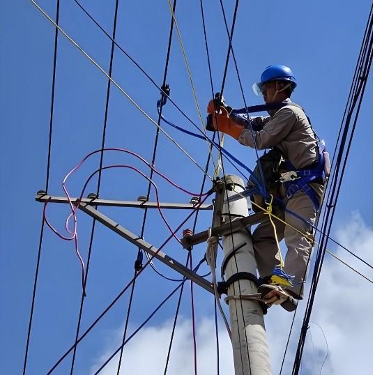
When lightning-induced overvoltage travels along overhead power lines into a substation or other buildings, it can cause flashovers or even puncture the insulation of electrical equipment. Therefore, if a protective device—known as a surge arrester—is connected in parallel at the power inlet of the equipment (as shown in Figure 1), it will immediately activate when the overvoltage reaches the preset operating level.
The arrester discharges the excess energy, limiting the voltage surge and protecting the equipment's insulation. Once the voltage returns to normal, the surge arrester quickly recovers its original state, ensuring the system can continue normal power supply.

The protective function of a surge arrester is based on three prerequisites:
Proper coordination between the volt-second characteristic of the arrester and that of the protected insulation.
The arrester's residual voltage must be lower than the impulse withstand strength of the protected insulation.
The protected insulation must be within the protective distance of the arrester.
Requirements for surge arresters:
It should not discharge under normal operating conditions, but must discharge correctly and reliably during overvoltage events.
It must have self-recovery capability after discharging (i.e., return to its high-impedance state and extinguish follow current).
Key parameters of surge arresters:
Continuous operating voltage: The allowable long-term operating voltage. It should be equal to or greater than the system's maximum phase-to-ground voltage.
Rated voltage (kV): The maximum allowable short-time power frequency voltage (also known as arc extinguishing voltage). The arrester can operate and extinguish the arc under this voltage, but cannot sustain long-term operation at this level. It is a fundamental parameter for arrester design, characteristics, and structure.
Power frequency withstand volt-second characteristic: Indicates the ability of a metal-oxide (e.g., ZnO) arrester to withstand overvoltages under specified conditions.
Nominal discharge current (kA): The peak value of discharge current used to classify arrester ratings. For systems 220 kV and below, it should not exceed 5 kA.
Residual voltage: The voltage that appears across the arrester terminals when subjected to a surge current. It can also be understood as the maximum voltage the arrester can withstand during a discharge event.

Types and Structure of Surge Arresters
Common types of surge arresters include valve-type, tube-type, protective gaps, and metal-oxide arresters.
(1) Valve-Type Surge Arresters
Valve-type arresters are mainly divided into two categories: conventional valve-type and magnetic-blow valve-type. The conventional type includes the FS and FZ series; the magnetic-blow type includes the FCD and FCZ series.
The symbols in the model designation stand for:
F – Valve-type arrester;
S – For distribution systems;
Z – For substations;
Y – For transmission lines;
D – For rotating machines;
C – With magnetic-blow discharge gap.
A valve-type arrester consists of flat spark gaps in series with silicon carbide (SiC) resistor discs (valve blocks), sealed inside a porcelain housing, with external terminal bolts for installation. The silicon carbide resistor exhibits nonlinear characteristics: it has high resistance under normal voltage, which decreases sharply during overvoltage.
Under normal power frequency voltage, the spark gaps remain non-conductive. When a lightning overvoltage occurs, the spark gaps break down. The resistance of the SiC blocks drops significantly, allowing the high lightning current to flow safely to ground. Following the surge, the SiC blocks present high resistance to the power frequency follow current, while the spark gaps interrupt this current, restoring normal system operation. This on-off behavior resembles a "valve"—open for lightning current and closed for power frequency current—hence the name "valve-type" arrester.
(2) Protective Gaps and Expulsion (Tube) Arresters
Protective gaps are the simplest form of lightning protection. Typically made of galvanized round steel, they consist of a main gap and an auxiliary gap. The main gap is shaped in an angular configuration and mounted horizontally to facilitate arc extinction. An auxiliary gap is connected in series below the main gap to prevent false triggering caused by foreign objects shorting the gap. Due to their weak arc-quenching capability, protective gaps are usually used in conjunction with automatic reclosing devices to improve power supply reliability.
The expulsion (tube-type) arrester consists of a spark gap housed within a gas-generating tube, formed by rod and ring electrodes. It includes both internal and external gaps. The arrester tube is made of materials such as fiber-reinforced phenolic resin that produce large volumes of gas when heated. When a lightning overvoltage occurs, both internal and external gaps break down, diverting the lightning current to ground. The subsequent power frequency current creates a strong arc, which burns the tube wall and generates high-pressure gas expelled through the open end, rapidly extinguishing the arc. The external gap then restores its insulation, isolating the arrester from the system and allowing normal operation to resume.
Since expulsion arresters rely on power frequency current to generate gas for arc extinction, excessive short-circuit currents can produce too much gas, exceeding the tube’s mechanical strength and causing rupture or explosion. Therefore, expulsion arresters are typically used in outdoor installations.
(3) Gapless Metal-Oxide (Zinc Oxide) Surge Arresters
Also known as varistor arresters, these are a modern type introduced in the 1970s. Compared to traditional silicon carbide valve-type arresters, gapless metal-oxide arresters have no spark gaps and use zinc oxide (ZnO) instead of silicon carbide. They are constructed from stacked ZnO varistor discs with excellent nonlinear voltage-current characteristics: under normal power frequency voltage, they exhibit very high resistance, effectively suppressing leakage current; under lightning overvoltage, their resistance drops sharply, allowing efficient discharge of surge current.
Metal-oxide arresters offer superior protection characteristics, high discharge capacity, low residual voltage, compact size, and easy installation. They are now widely used for protection of both high- and low-voltage electrical equipment.
(4) Gapped Metal-Oxide (Zinc Oxide) Surge Arresters
These consist of ZnO resistor discs connected in series with a spark gap inside a composite housing. The gap unit typically contains two disc-shaped electrodes enclosed in a ceramic ring. They are suitable for non-effectively grounded neutral systems. During single-phase-to-ground faults or arc grounding, severe transient overvoltages of long duration may occur, which gapless ZnO arresters may not withstand. Gapped ZnO arresters overcome this limitation: under moderate overvoltages such as single-phase grounding or low-level arc grounding, the series gap remains inactive, isolating the arrester from the system.
When the overvoltage exceeds a threshold, the gap sparks over, and the excellent nonlinear characteristics of the ZnO blocks limit the residual voltage across the arrester. The resulting follow current is very small and easily interrupted, providing reliable insulation protection for transformers and other equipment.

Test Items and Standards for Surge Arresters
(1) Insulation Resistance Measurement
Use a megohmmeter of 2500 V or higher. For arresters rated 35 kV and above, the insulation resistance should be no less than 2500 MΩ; for those below 35 kV, no less than 1000 MΩ.
(2) Measurement of DC Voltage at 1 mA and Leakage Current at 75% of This Voltage
Apply a DC voltage to the arrester. As the voltage increases, the leakage current gradually rises. Record the voltage value when the current reaches 1 mA. Then reduce the voltage to 75% of this value and record the leakage current, which should not exceed 50 μA.
(3) AC Leakage Current under Operating Voltage
Measure the total current, resistive current, or power loss under operating voltage. The measured values should show no significant change compared to initial values. If the resistive current doubles, the arrester must be de-energized for inspection.
If the resistive current increases to 150% of the initial value, the monitoring cycle should be appropriately shortened.
These tests can detect defects such as moisture ingress or aging of arrester valve blocks, surface cracks, and insulation deterioration.