Surge Arresters and Their Evolution
A surge arrester is always connected in parallel with the electrical equipment it protects. It does not interfere with the equipment's normal operation at system voltage. However, when a dangerous overvoltage appears on the equipment, the arrester conducts first, diverting the overvoltage safely into the ground.
The earliest and simplest form of surge arrester consisted of two metal rods separated by a gap and connected in parallel across electrical equipment. When the voltage across this gap exceeded a certain threshold, the air (the gap) would break down, protecting the equipment. This type of arrester is known as an "expulsion gap" or "protective gap."
The phenomenon of lightning is similar: thunderclouds and the earth act as two conductors (electrodes). When the voltage between them becomes too high, the air between them breaks down, resulting in a lightning strike.
However, there is a crucial difference. Protective gaps are connected directly across power lines. Once a dangerous overvoltage causes the gap to break down (i.e., the air between the rods is ionized), the power plant or substation is unaware of this event—or cannot react quickly enough. Consequently, it continues to supply current to the now-conducting gap. Since the gap provides a path to ground, this current flows continuously, causing a short circuit in the power system. Thus, while protective gaps are simple to use, their operation creates a sustained arc across the gap, leading to a short-circuit condition.
How could the arc across the protective gap be extinguished quickly after operation? This led to the development of the second-generation arrester—the expulsion (or tube-type) arrester. This design first confines the arc within a tube and then employs methods to extinguish it.
Nevertheless, expulsion arresters still have a drawback: regardless of their arc-quenching capability, they still divert power system current directly to ground, causing a momentary earth fault (short circuit).
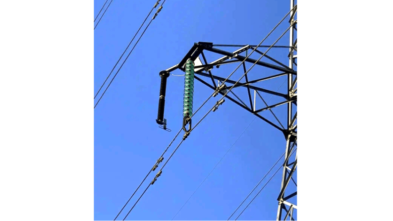
An ideal solution would be a device that blocks current or allows only minimal leakage under normal voltage, thus avoiding short circuits, but rapidly conducts large surge currents (like lightning) to ground when dangerous overvoltages occur. In simple terms, such a device would act like an "intelligent switch," knowing precisely when to open and close. In surge arresters, this "intelligent switch" was initially realized using a material called silicon carbide (SiC). Arresters made from this material are known as valve-type arresters, as they function like electrical valves.
It is important to note that this "valve" is an electrical component, not a mechanical valve like a faucet or pipe valve. Mechanical valves are far too slow to respond to lightning, which strikes in microseconds. Instead, an electrical "valve" made of a non-linear resistor is required. Silicon carbide was the first non-linear resistor material discovered for use in high-voltage applications.
Technology evolves continuously. A second non-linear resistor material was later discovered for surge arresters: zinc oxide (ZnO). It performs a similar function to silicon carbide but exhibits superior "valve" characteristics—professionally described as having better non-linearity.
What is non-linearity? Figuratively, it means doing the opposite: being small when it should be large, and large when it should be small—unlike linear components, which scale proportionally.
In surge arresters, non-linearity manifests as follows: when current is high (e.g., during a lightning surge), the resistance becomes very low, and the lower the resistance, the better the non-linearity. When current is low (after the lightning surge has passed and the system returns to normal operating voltage), the resistance becomes very high, and the higher the resistance, the better the non-linearity.
Silicon carbide exhibits non-linearity, but it is not ideal. Under normal operating voltage, its resistance is not sufficiently high, allowing a small leakage current to flow through the arrester—like a valve that does not close tightly, resulting in a continuous "trickle" of current.
This behavior is inherent to the material, and efforts to eliminate this leakage through material improvements have been largely unsuccessful. Consequently, when using silicon carbide in arresters, structural solutions are employed: the arrester is initially isolated from the line and only connected during a surge. This task is accomplished using a series air gap. Therefore, valve-type arresters almost always require a gap. In contrast, zinc oxide valves "close tightly" under normal operating voltage, so they do not require a series gap.
As zinc oxide manufacturing technology has improved, early limitations in "closing" capability have been overcome. However, due to the historical prevalence of gapped designs, some zinc oxide arresters still incorporate gaps. Nevertheless, gapless zinc oxide arresters constitute the vast majority.
Since zinc oxide is a metal oxide, these arresters are also known as Metal Oxide Surge Arresters (MOSA).
Lightning Protection in Power Systems
From the perspective of lightning protection devices, three main types exist: lightning rods (air terminals), overhead ground wires (shield wires), and surge arresters. The first two are structurally simple—essentially just rods and wires—while the latter is more complex due to its reliance on non-linear resistors acting as "intelligent switches."
From the perspective of protected objects, lightning protection can be categorized into: overhead transmission line protection, substation protection, and motor protection.
Overhead lines span vast distances, exposed in open areas. To minimize impact on terrestrial life and ecosystems, they are erected at significant heights. As the saying goes, "The tallest tree catches the most wind," making them prime targets for lightning. Statistics show that the majority of power grid failures are caused by lightning strikes on lines. Therefore, overhead lines must be protected. However, due to their length, absolute protection is impractical and prohibitively expensive. Thus, line protection is relative: some lightning strikes are allowed to hit the line and cause flashovers. This protection is primarily achieved using overhead ground wires.
In contrast, substations are far more critical. They serve as hubs of the power system, housing concentrated equipment and personnel. Consequently, their lightning protection requirements are extremely high.
Lightning can reach a substation via two main paths: direct strikes, mitigated by lightning rods (or sometimes shield wires); and surges propagating from lightning strikes on transmission lines, which are primarily handled by surge arresters.
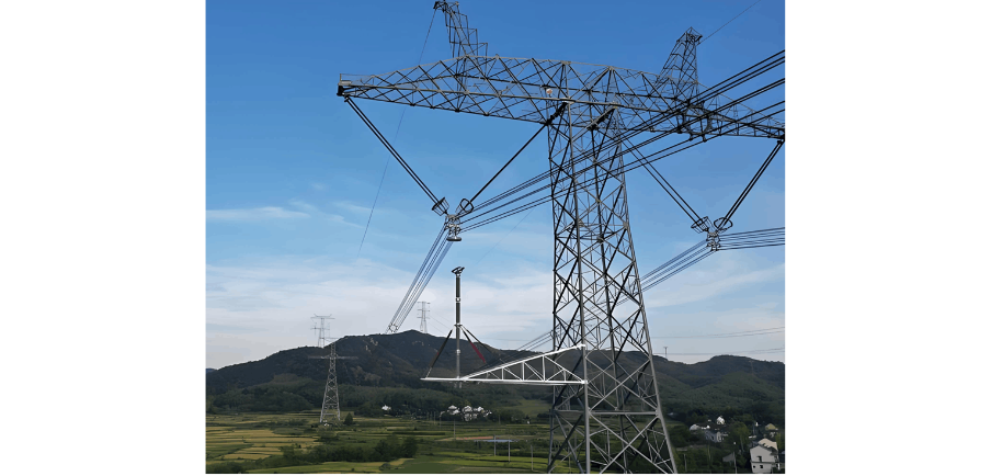
Lightning protection for motors (including generators, synchronous condensers, frequency changers, and electric motors) is as critical as substation protection. Generators are the "heart" of the power system, and large motors are vital industrial drivers. Lightning damage to these components results in significant losses. However, motor protection is more challenging than substation protection. Motors are rotating machines, so their insulation cannot be excessively thick and must be solid (unlike the liquid insulation used in transformers). Solid insulation is prone to aging, necessitating not only primary protection with surge arresters but also additional auxiliary protective measures.
Composite-Housed Zinc Oxide Surge Arresters
A surge arrester is an electrical device with two electrodes—one typically grounded and the other connected to high voltage—separated by an insulating material, known professionally as an insulator.
Since most power system equipment is exposed to the atmosphere, the insulating surfaces are in direct contact with the environment. This portion of insulation is termed external insulation or outdoor insulation.
Outdoor insulation is constantly exposed to sunlight, rain, wind, snow, fog, and dew. Therefore, qualified outdoor insulation materials must not only possess excellent electrical and mechanical properties but also demonstrate superior weather resistance and a service life of 40–50 years. Currently, porcelain is the most widely used outdoor insulation material in engineering, with tempered glass also used in line applications.
Porcelain and glass are inorganic materials. Besides their excellent electrical and mechanical performance, their key advantage is environmental stability—exceptional resistance to climatic conditions—enabling them to dominate power system external insulation for nearly a century.
However, they share a common weakness: their surfaces are hydrophilic. This allows pollution layers on the insulator surface to absorb moisture. When pollution combines with moisture, it enables current flow, potentially causing a flashover across the insulator surface under normal operating voltage. This is commonly known as pollution flashover, more specifically, surface discharge along a polluted and wetted insulator.
In recent decades, silicone rubber has been widely adopted worldwide to replace traditional materials for insulators. Silicone rubber is an organic material exhibiting strong hydrophobicity, significantly increasing the pollution flashover voltage of external insulation.
Insulators made from organic materials are often called polymer insulators (as organic materials are polymers), non-ceramic insulators, composite insulators (since the external insulation is synthetic), or even plastic insulators abroad.
In China, they were previously known as composite insulators or silicone rubber insulators. They are now uniformly termed organic composite insulators (since organic materials are composites, and these insulators are typically made from a composite of silicone rubber and an epoxy-resin-glass-fiber rod), commonly abbreviated as composite insulators.
Therefore, a composite-housed zinc oxide surge arrester uses an organic material—specifically silicone rubber—as the external insulation for a zinc oxide surge arrester.


