• Product
  • Suppliers
  • Manufacturers
  • Solutions
  • Free tools
  • Knowledges
  • Experts
  • Communities
Search


Should the earthing switch be properly designed to take the fault current at the point of insulation?

Encyclopedia
Encyclopedia
Field: Encyclopedia
0
China

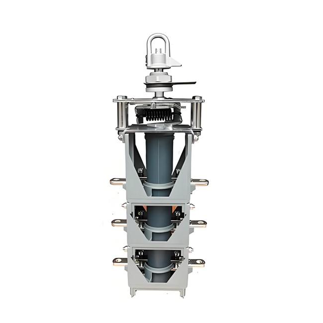
Earthing switches (or grounding switches) are designed to provide a safety measure within electrical systems, ensuring that electrical equipment can be reliably earthed during maintenance or other operations, thereby protecting personnel and equipment. Regarding whether grounding switches should be designed to absorb fault currents at insulation points, this involves understanding the function and design specifications of grounding switches.

Function of Earthing Switches

The primary functions of grounding switches include:

  • Safe Earthing: Ensuring that circuits can be reliably earthed during maintenance or inspections to prevent accidental electrocution.

  • Fault Current Path: Providing a low-impedance path during faults, allowing fault currents to safely flow to ground and triggering the operation of protective devices (such as circuit breakers tripping).

Absorbing Fault Currents

Grounding switches are not designed to "absorb" fault currents. Their purpose is to ensure that, in the event of a fault, the fault current can quickly flow through the grounding switch, causing protective devices to act swiftly by isolating the power supply. In other words, the role of the grounding switch is to provide a low-impedance path rather than to absorb or dissipate fault currents.

Design Specifications

The design of grounding switches must comply with relevant international and national standards, such as those set by the International Electrotechnical Commission (IEC) or other regional electrical safety codes. These standards typically specify parameters for the grounding switch, including rated current, short-circuit current capability, and other electrical and mechanical performance criteria.

Key Factors

When designing grounding switches, several key factors need to be considered:

1. Rated Current 

The maximum continuous current the grounding switch can handle.

2. Short-Circuit Current 

The maximum expected short-circuit current the grounding switch can withstand without being damaged (typically for a few seconds).

3. Mechanical Strength

The grounding switch must have sufficient mechanical strength to ensure it does not break or deform during operation.

4. Operational Reliability

The grounding switch must be able to close and open reliably, especially in emergency situations.

Other Measures for Absorbing Fault Currents

While grounding switches themselves are not designed to absorb fault currents, there are other devices specifically engineered to handle or manage fault currents in electrical systems, such as:

  • Fuses: Used for overload and short-circuit protection.

  • Circuit Breakers : Used for overload and short-circuit protection and can quickly isolate the circuit upon detecting a fault current.

  • Surge Protectors : Used to absorb overvoltages and transient currents.

Summary

The design of grounding switches is primarily aimed at providing a reliable earthing path to ensure that, in case of a fault, the power supply can be rapidly isolated. They are not designed to absorb fault currents but instead ensure that fault currents can flow through a low-impedance path to ground, thereby triggering the action of protective devices. To ensure the safety of electrical systems, besides grounding switches, other protective measures are needed to work together effectively.

If you have any further questions or need additional information, please feel free to ask!


Give a tip and encourage the author!
Recommended
 Causes and Preventive Measures of Fire and Explosion in Oil Circuit Breakers
Causes and Preventive Measures of Fire and Explosion in Oil Circuit Breakers
Causes of Fire and Explosion in Oil Circuit Breakers When the oil level in an oil circuit breaker is too low, the oil layer covering the contacts becomes too thin. Under the effect of the electric arc, the oil decomposes and releases flammable gases. These gases accumulate in the space beneath the top cover, mixing with air to form an explosive mixture, which can ignite or explode under high temperature. If the oil level inside the tank is too high, the released gases have limited space to expan
Felix Spark
11/06/2025
What are the common faults encountered during the operation of power transformer longitudinal differential protection?
Transformer Longitudinal Differential Protection: Common Issues and SolutionsTransformer longitudinal differential protection is the most complex among all component differential protections. Misoperations occasionally occur during operation. According to 1997 statistics from the North China Power Grid for transformers rated 220 kV and above, there were 18 incorrect operations in total, of which 5 were due to longitudinal differential protection—accounting for approximately one-third. Causes of
Felix Spark
11/05/2025
Relay Protection Types in Substations: A Complete Guide
(1) Generator Protection:Generator protection covers: phase-to-phase short circuits in stator windings, stator ground faults, inter-turn short circuits in stator windings, external short circuits, symmetrical overload, stator overvoltage, single- and double-point grounding in the excitation circuit, and loss of excitation. Tripping actions include shutdown, islanding, limiting fault impact, and alarm signaling.(2) Transformer Protection:Power transformer protection includes: phase-to-phase short
Echo
11/05/2025
What Are the Factors Influencing the Impact of Lightning on 10kV Distribution Lines?
1. Induced Lightning OvervoltageInduced lightning overvoltage refers to the transient overvoltage generated on overhead distribution lines due to nearby lightning discharges, even when the line is not directly struck. When a lightning flash occurs in the vicinity, it induces a large amount of charge on the conductors—opposite in polarity to the charge in the thundercloud.Statistical data shows that lightning-related faults caused by induced overvoltages account for approximately 90% of total fau
Echo
11/03/2025
Related Products
Send inquiry
Download
Get the IEE Business Application
Use the IEE-Business app to find equipment, obtain solutions, connect with experts, and participate in industry collaboration anytime, anywhere—fully supporting the development of your power projects and business.