• Product
  • Suppliers
  • Manufacturers
  • Solutions
  • Free tools
  • Knowledges
  • Experts
  • Communities
Search


What are the signs that a multimeter is out of calibration?

Encyclopedia
Field: Encyclopedia
0
China

Signs of an Un-Calibrated Multimeter

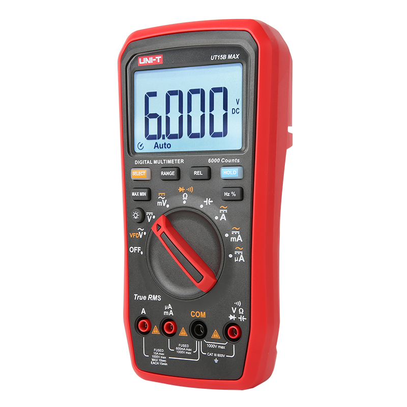
A multimeter is an essential tool used to measure electrical parameters such as voltage, current, and resistance. If a multimeter has not been properly calibrated, it can lead to inaccurate measurements, which in turn can affect fault diagnosis and repair work. Below are some common signs that indicate a multimeter may be un-calibrated:

1. Unstable Measurements

  • Fluctuating Readings: When measuring the same circuit or component, the multimeter displays readings that fluctuate and do not stabilize. This could be due to aging internal components or faulty sensors, leading to inconsistent measurements.

  • Poor Repeatability: Multiple measurements of the same parameter yield significantly different results, lacking consistency.

2. Significant Measurement Deviations

  • Discrepancy with Known Standards: If you measure a known standard source (such as a regulated power supply or a standard resistor) and the reading deviates noticeably from the expected value, this may indicate an un-calibrated multimeter.

  • Exceeding Tolerance Range: Multimeters typically have a specified measurement error range. If the readings frequently exceed this range, especially in applications requiring high precision, it may suggest the need for calibration.

3. Zero Drift

  • Unable to Zero: When measuring resistance, shorting the test probes together (i.e., measuring zero ohms) should result in a reading of zero. If the multimeter shows a small non-zero value, it may indicate internal circuit offset or sensor degradation.

  • Failed Auto-Zero Function: Some multimeters have an auto-zero function, which, if malfunctioning, can lead to inaccurate measurements.

4. Abnormal Range Selection

  • Failed Auto-Range Function: If the multimeter has an auto-range feature but fails to select the appropriate measurement range correctly or shows significant delays or errors when switching ranges, it may be un-calibrated.

  • Inaccurate Manual Range Selection: When manually selecting ranges, the readings do not match the actual values, especially when switching between different ranges, indicating potential calibration issues.

5. Insufficient Battery Power

Low Battery Affecting Accuracy: While not strictly a "calibration" issue, insufficient battery power can affect the accuracy of measurements. If the multimeter's battery is low, it may produce unstable or inaccurate readings. Ensuring the battery is fully charged or replaced is crucial for maintaining measurement accuracy.

6. Environmental Factors

  • Temperature Sensitivity: Some multimeters are sensitive to temperature changes. If used in extreme temperatures, they may produce inaccurate readings. If the multimeter was calibrated at a specific temperature and is now used in a significantly different environment, measurement deviations can occur.

  • Humidity and Dust Impact: High humidity or dusty environments can affect the internal circuits of the multimeter, leading to inaccurate measurements. Regular cleaning and maintenance can mitigate these effects.

7. Expired Calibration Label

  • Expired Calibration Certificate: Many professional-grade multimeters come with a calibration certificate that indicates the date of the last calibration and its validity period. If the calibration certificate has expired, it is advisable to have the multimeter re-calibrated to ensure accurate measurements.

  • No Calibration Record: If your multimeter lacks a calibration record or has never been calibrated, its accuracy may be unreliable, especially in applications requiring high precision.

8. Inconsistent Results Compared to Other Devices

  • Comparison with Other Multimeters: If you have multiple multimeters or other measurement devices, compare their readings. If one multimeter's readings differ significantly from others, it may need calibration.

  • Comparison with a Known Good Device: Use a known good multimeter or measurement device as a reference and compare the readings. Significant differences suggest that the un-calibrated multimeter may have issues.

9. Abnormal Extreme Value Measurements

  • Unable to Measure Extreme Values: When attempting to measure values close to the multimeter's range limits, the readings may be abnormal or fail to display. For example, measuring very high voltages or very low resistances may yield inaccurate results.

  • Incorrect Overrange Indication: The multimeter should clearly indicate when a measurement exceeds its range (e.g., with "OL" or "Overload"). If it fails to provide this indication or shows incorrect messages when within range, it may be un-calibrated.

10. Physical Damage or Abnormal Appearance

  • Physical Damage: If the multimeter's housing shows visible physical damage (such as cracks or deformations), it may affect the internal circuits' performance, leading to inaccurate measurements.

  • Damaged Probes or Leads: Damaged probes or connecting wires (such as broken or corroded connections) can also cause inaccurate readings. Inspecting the probes and leads for integrity is crucial for ensuring accurate measurements.

Summary

Signs of an un-calibrated multimeter include unstable measurements, significant deviations, zero drift, abnormal range selection, insufficient battery power, environmental factors, expired calibration labels, inconsistent results compared to other devices, abnormal extreme value measurements, and physical damage or abnormal appearance. To ensure the accuracy of your multimeter, regular calibration is essential, especially in applications requiring high precision. If you observe any of these signs, it is advisable to have the multimeter calibrated or contact a professional technician for inspection and repair.

Give a tip and encourage the author!
Recommended
Transmission Line
In transmission lines, a "π" connection involves breaking the original line from Substation A to Substation B and inserting Substation C, forming a "π" configuration. After the "π" connection, the original single line is divided into two independent transmission lines. Following the "π" connection, Substations B and C may both be powered by Substation A (in this case, Substation C receives power via a feeder from Substation B's busbar, or possibly from another voltage point within Substation B);
Encyclopedia
09/04/2025
What are the principles of forced re-energization of transmission lines?
Principles of Forced Re-energization of Transmission LinesRegulations for Forced Re-energization of Transmission Lines Correctly select the forced re-energization end of the line. If necessary, change the connection configuration before forced re-energization, taking into account the reduction of short-circuit capacity and its impact on grid stability. There must be a transformer with its neutral point directly grounded on the busbar at the forced re-energization end. Pay attention to the impact
Edwiin
09/04/2025
Analysis of Accident Handling in Transmission Lines
Analysis of Transmission Line Fault HandlingAs a fundamental component of the power grid, transmission lines are widely distributed and numerous, often exposed to diverse geographical and climatic conditions, making them highly susceptible to faults. Common causes include overvoltage, pollution flashover, insulation damage, tree encroachment, and external damage. Line tripping is one of the most frequent faults in power plant and substation operations, with fault types including single-phase-to-
Leon
09/04/2025
The difference between transmission and distribution lines
Transmission lines and distribution lines are both used to carry electrical power from one location to another. However, they differ significantly in key aspects such as primary function, voltage levels, phase configuration, and conductor placement. These differences are essential for understanding their distinct roles in the power system.The Difference Between Transmission and Distribution Line is given below in the tabulated form.Electricity generation is a critical component of the power syst
Edwiin
09/04/2025
Related Products
  • Advance Earth Resistance Tester Digital Ground Resistance Test/Soil Resistivity Test Data Storage LCD Backlight
  • AC voltage detector pen Tester with vibration mode HLX
  • The Voltage Tester 6V-400V Electricians And DIYers To Measure AC/DC Voltage
  • Wire Tracer for Underground and Wall Electrical Wires and Pipes
Seed Inquiry
Download
Get the IEE Business Application
Use the IEE-Business app to find equipment, obtain solutions, connect with experts, and participate in industry collaboration anytime, anywhere—fully supporting the development of your power projects and business.