From Coils to Current: The Evolution of Transformer Engineering
In the realm of electrical engineering, few inventions have had as profound an impact as the transformer. It stands as a silent yet indispensable force, enabling the efficient transmission and distribution of electrical power. Delving into the intricate world of transformer engineering, we embark on a journey from the early days of coiled wonders to the current state of advanced technology, witnessing the evolution that has shaped our modern power systems.
The Birth of Coils: Early Transformer Origins
The story begins in the late 19th century, when the pioneering work of visionaries like Michael Faraday and Nikola Tesla laid the foundation for the transformer. Coils of wire wound around iron cores formed the initial building blocks, with the fundamental principles of electromagnetic induction becoming the cornerstone of transformer design. Early transformers were relatively simple in structure, but their ability to alter voltage levels with minimal power loss captivated engineers.
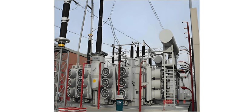
Rise of the Power Grid: Transformers in the Electrification Era
As the world embraced electrification, transformers played a pivotal role in establishing power grids. The capability to step up voltage for efficient long-distance transmission and step it down for safe end-user distribution became crucial. This era marked the transformation of transformers from experimental devices into essential components of burgeoning electrical systems, fueling industrial and urban growth.
Advancements in Core Materials: Beyond Iron Coils
The pursuit of efficiency and compact design drove innovations in transformer materials. While iron remained fundamental, the development of alternative core materials—such as specialized alloys and laminations—enhanced performance and reduced energy losses. The evolution of core materials became a key chapter in transformer engineering, enabling more reliable and lightweight designs.
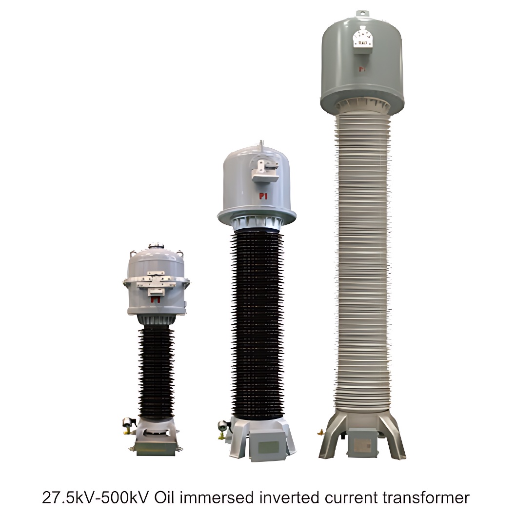
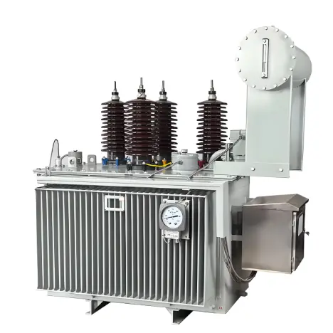
Oil Immersion and Cooling Systems: Enhancing Transformer Reliability
The mid-20th century saw another significant leap with the introduction of oil-immersed transformers. This innovation provided superior insulation and improved cooling, allowing transformers to handle higher loads with greater reliability. The development of advanced cooling systems became paramount, especially for transformers operating under heavy loads and challenging conditions.
Digital Era Transformation: Smart Transformers for Smart Grids
Venturing into the 21st century, the digital revolution has left an indelible mark on transformer engineering. Smart transformers, equipped with monitoring and control capabilities, have emerged, ushering in an era of predictive maintenance and real-time performance optimization. The integration of sensors and communication technologies enables these transformers to communicate with the grid, providing valuable data for efficient management and troubleshooting.
Looking to the Future: Sustainable and Resilient Power
The evolution of transformer engineering continues, driven by the imperative to create a sustainable and resilient power infrastructure. Researchers and engineers are exploring eco-friendly materials, innovative cooling techniques, and advanced insulation methods to push the boundaries of efficiency and environmental consciousness. The future promises transformers that not only meet the growing demands of power systems but also contribute to a greener, more sustainable energy landscape.
In conclusion, the journey from coils to current in transformer engineering is a testament to human ingenuity and the relentless pursuit of efficiency in power transmission. As transformers evolve to meet modern challenges, they remain a silent force, shaping how electricity powers our world. The story is far from over, and the next chapter holds the promise of even more transformative innovations in this dynamic field.


![SY Series 35KV On-load Tap Changer [OLTC]](https://oss.iwone.cn/img/prod/202507/1753316159185.png)