In the realm of electrical engineering, few inventions have had as profound an impact as the transformer. It stands as a silent yet indispensable force, enabling the efficient transmission and distribution of electrical power. Exploring the intricate world of transformer engineering reveals a journey from the early days of coiled wonders to today’s advanced technologies—evolution that has fundamentally shaped modern power systems.
The Birth of Coils: Early Transformer Origins
The story begins in the late 19th century, when pioneering work by visionaries such as Michael Faraday and Nikola Tesla laid the foundation for the transformer’s invention. Coils of wire wound around iron cores formed the earliest designs, with electromagnetic induction establishing the core principle of transformer operation. Though structurally simple, these early devices demonstrated the revolutionary ability to change voltage levels with minimal power loss—capturing the imagination and driving innovation among engineers.
Rise of the Power Grid: Transformers in the Electrification Era
As electrification spread worldwide, transformers became pivotal in building power grids. Their ability to step up voltage for efficient long-distance transmission and step it down for safe local distribution proved essential. This era marked the transition of transformers from experimental curiosities to critical components of expanding electrical infrastructure, powering industrial growth and urban development.
Advancements in Core Materials: Beyond Iron Coils
The pursuit of higher efficiency and more compact designs spurred innovation in core materials. While iron remained fundamental, the development of specialized alloys and laminated cores significantly improved performance and reduced energy losses. These material advancements became a cornerstone of transformer engineering, enabling more reliable, efficient, and lightweight designs.
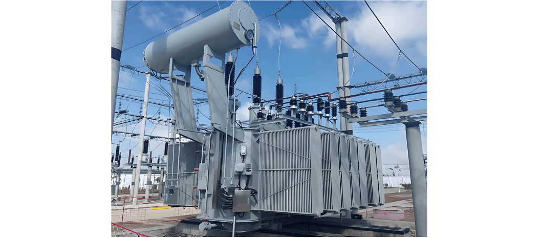
Oil Immersion and Cooling Systems: Enhancing Transformer Reliability
A major leap occurred in the mid-20th century with the adoption of oil-immersed transformers. This design enhanced both insulation and cooling, allowing transformers to handle higher loads with greater reliability. The evolution of advanced cooling systems became essential, particularly for installations facing heavy loads and harsh operating conditions.
Digital Era Transformation: Smart Transformers for Smart Grids
Entering the 21st century, the digital revolution has transformed transformer engineering. Smart transformers—embedded with sensors, monitoring systems, and communication capabilities—now enable predictive maintenance and real-time performance optimization. Integrated into smart grids, they provide critical data for grid management, fault detection, and system efficiency.
Looking to the Future: Sustainable and Resilient Power
Transformer engineering continues to evolve, driven by the need for sustainable and resilient power infrastructure. Researchers are exploring eco-friendly materials, novel cooling methods, and advanced insulation technologies to further improve efficiency and reduce environmental impact. The future promises transformers that not only meet rising energy demands but also support a cleaner, greener energy ecosystem.
In conclusion, the journey from simple coils to modern high-performance transformers exemplifies human ingenuity and the relentless pursuit of efficiency in power transmission. As transformers adapt to the challenges of the digital and sustainable age, they remain a quiet yet powerful force—shaping how electricity powers our world. The story is far from over; the next chapter holds the promise of even more transformative innovations in this dynamic field.