• Product
  • Suppliers
  • Manufacturers
  • Solutions
  • Free tools
  • Knowledges
  • Experts
  • Communities
Search


Characteristics of a Solar Cell and Parameters of a Solar Cell

Electrical4u
Electrical4u
Field: Basic Electrical
0
China

WechatIMG1804.jpeg

Solar cell is the basic unit of solar energy generation system where electrical energy is extracted directly from light energy without any intermediate process. The working of a solar cell solely depends upon its photovoltaic effect hence a solar cell also known as photovoltaic cell. A solar cell is basically a semiconductor device. The solar cell produce electricity while light strikes on it and the voltage or potential difference established across the terminals of the cell is fixed to 0.5 volt and it is nearly independent of intensity of incident light whereas the current capacity of cell is nearly proportional to the intensity of incident light as well as the area that exposed to the light. Each of the solar cells has one positive and one negative terminal like all other type of battery cells. Typically a solar or photovoltaic cell has negative front contact and positive back contact. A semiconductor p-n junction is in the middle of these two contacts.

While sunlight falling on the cell the some photons of the light are absorbed by solar cell. Some of the absorbed photons will have energy greater than the energy gap between valence band and conduction band in the semiconductor crystal. Hence, one valence electron gets energy from one photon and becomes excited and jumps out from the bond and creates one electron-hole pair. These electrons and holes of e-h pairs are called light-generated electrons and holes. The light-generated electrons near the p-n junction are migrated to n-type side of the junction due to electrostatic force of the field across the junction. Similarly the light-generated holes created near the junction are migrated to p-type side of the junction due to same electrostatic force. In this way a potential difference is established between two sides of the cell and if these two sides are connected by an external circuit current will start flowing from positive to negative terminal of the solar cell. This was basic working principle of a solar cell now we will discuss about different parameters of a solar or photovoltaic cell upon which the rating of a solar panel depends. During choosing a particular solar cell for specific project it is essential to know the ratings of a solar panel. These parameters tell us how efficiently a solar cell can convert the light to electricity.

Short Circuit Current of Solar Cell

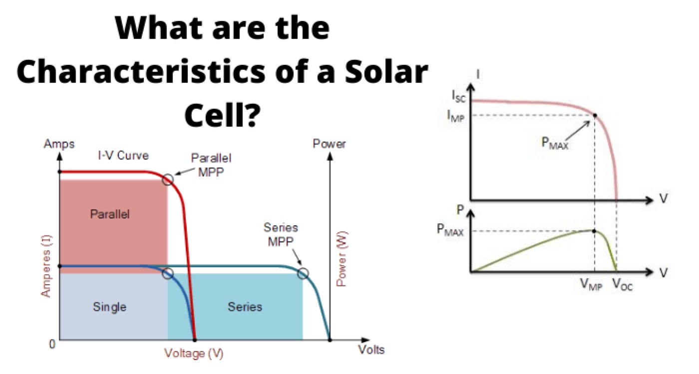
The maximum current that a solar cell can deliver without harming its own constriction. It is measured by short circuiting the terminals of the cell at most optimized condition of the cell for producing maximum output. The term optimized condition I used because for fixed exposed cell surface the rate of production of current in a solar cell also depends upon the intensity of light and the angle at which the light falls on the cell. As the current production also depends upon the surface area of the cell exposed to light, it is better to express maximum current density instead maximum current. Maximum current density or short circuit current density rating is nothing but ration of maximum or short circuit current to exposed surface area of the cell.

Where, Isc is short circuit current, Jsc maximum current density and A is the area of solar cell.

Open Circuit Voltage of Solar Cell

It is measured by measuring voltage across the terminals of the cell when no load is connected to the cell. This voltage depends upon the techniques of manufacturing and temperature but not fairly on the intensity of light and area of exposed surface. Normally open circuit voltage of solar cell nearly equal to 0.5 to 0.6 volt. It is normally denoted by Voc.

Maximum Power Point of Solar Cell

The maximum electrical power one solar cell can deliver at its standard test condition. If we draw the v-i characteristics of a solar cell maximum power will occur at the bend point of the characteristic curve. It is shown in the v-i characteristics of solar cell by Pm.
characteristics curve of solar cell

Current at Maximum Power Point

The current at which maximum power occurs. Current at Maximum Power Point is shown in the v-i characteristics of solar cell by Im.

Voltage at Maximum Power Point

The voltage at which maximum power occurs. Voltage at Maximum Power Point is shown in the v-i characteristics of solar cell by Vm.

Fill Factor of Solar Cell

The ratio between product of current and voltage at maximum power point to the product of short circuit current and open circuit voltage of the solar cell.

Efficiency of Solar Cell

It is defined as the ratio of maximum electrical power output to the radiation power input to the cell and it is expressed in percentage. It is considered that the radiation power on the earth is about 1000 watt/square metre hence if the exposed surface area of the cell is A then total radiation power on the cell will be 1000 A watts. Hence the efficiency of a solar cell may be expressed as

Statement: Respect the original, good articles worth sharing, if there is infringement please contact delete.

Give a tip and encourage the author!
Recommended
THD Measurement Error Standards for Power Systems
Error Tolerance of Total Harmonic Distortion (THD): A Comprehensive Analysis Based on Application Scenarios, Equipment Accuracy, and Industry StandardsThe acceptable error range for Total Harmonic Distortion (THD) must be evaluated based on specific application contexts, measurement equipment accuracy, and applicable industry standards. Below is a detailed analysis of key performance indicators in power systems, industrial equipment, and general measurement applications.1. Harmonic Error Standar
Edwiin
11/03/2025
Busbar-Side Grounding for 24kV Eco-Friendly RMUs: Why & How
Solid insulation assistance combined with dry air insulation is a development direction for 24 kV ring main units. By balancing insulation performance and compactness, the use of solid auxiliary insulation allows passing insulation tests without significantly increasing phase-to-phase or phase-to-ground dimensions. Encapsulation of the pole can address the insulation of the vacuum interrupter and its connected conductors.For the 24 kV outgoing busbar, with the phase spacing maintained at 110 mm,
Dyson
11/03/2025
How Vacuum Tech Replaces SF6 in Modern Ring Main Units
Ring main units (RMUs) are used in secondary power distribution, directly connecting to end-users such as residential communities, construction sites, commercial buildings, highways, etc.In a residential substation, the RMU introduces 12 kV medium voltage, which is then stepped down to 380 V low voltage through transformers. The low-voltage switchgear distributes electrical energy to various user units. For a 1250 kVA distribution transformer in a residential community, the medium-voltage ring m
James
11/03/2025
What Is THD? How It Affects Power Quality & Equipment
In the field of electrical engineering, the stability and reliability of power systems are of paramount importance. With the advancement of power electronics technology, the widespread use of nonlinear loads has led to an increasingly serious problem of harmonic distortion in power systems.Definition of THDTotal Harmonic Distortion (THD) is defined as the ratio of the root mean square (RMS) value of all harmonic components to the RMS value of the fundamental component in a periodic signal. It is
Encyclopedia
11/01/2025
Send inquiry
Download
Get the IEE Business Application
Use the IEE-Business app to find equipment, obtain solutions, connect with experts, and participate in industry collaboration anytime, anywhere—fully supporting the development of your power projects and business.