Medium voltage transformer inrush current mitigation by control switching device


Controlled Switching Devices in the Medium Voltage Range
Over three decades ago, Controlled Switching Devices (CSDs) were first introduced to mitigate switching transients caused by high voltage circuit breakers connected to shunt reactors and capacitor banks. Subsequent research expanded their application to transmission lines and power transformers. Initially, these devices optimized switching moments on a per-phase basis using independently pole-operated circuit breakers (IPO).
Recently, the surge in global energy demand has spurred the integration of renewable energy sources into medium voltage distribution grids rather than solely relying on high voltage (HV) transmission systems. This shift has necessitated addressing voltage dip issues stemming from uncontrolled inrush currents during transformer energization.
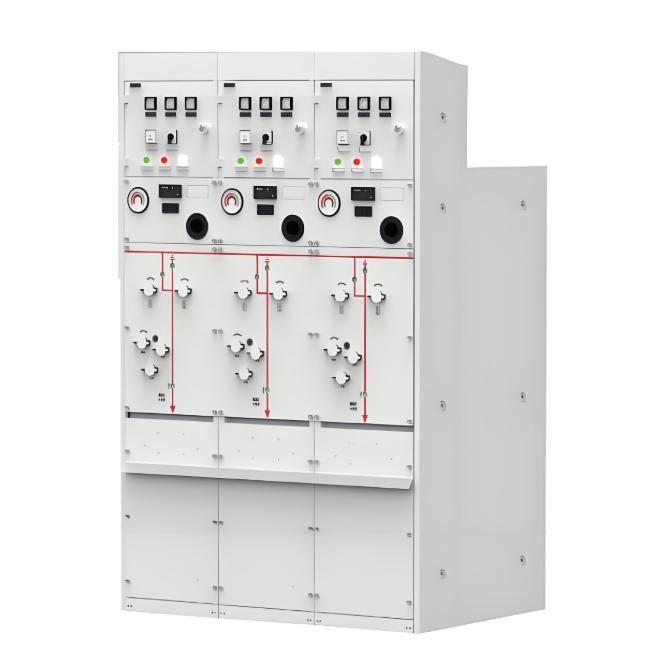
Medium voltage switchgear typically operates with three poles simultaneously, which contrasts with the independent operation in HV applications. This required significant advancements in CSD technology to effectively manage transformer energization inrush currents using standard switches with simultaneous pole operation. Today, this innovation is widely utilized not only in renewable energy installations like wind farms and photovoltaic solar plants but also in industrial setups and transportation networks, where controlling inrush currents is crucial for the reliable energization of both medium and high voltage transformers.
Inrush Current in Medium Voltage Transformers
The magnitude of the inrush current during transformer energization is significantly influenced by residual flux within the transformer core; higher residual flux levels can lead to greater inrush currents upon random energization. Effective mitigation strategies are essential to avoid operational disturbances and ensure grid stability.
By implementing advanced controlled switching techniques, it's possible to minimize or eliminate these inrush currents. These methods not only enhance system reliability but also extend equipment lifespan, reduce maintenance costs, and improve overall efficiency in medium voltage distribution grids. The adoption of such technologies marks a pivotal advancement in adapting to the evolving demands of modern electrical distribution networks.
Relationship Between Residual Flux and Transformer Inrush Current
Field data collected during the commissioning of Controlled Switching Devices (CSDs) on circuit breakers and switchgear with simultaneous pole operation has verified the relationship between residual flux and transformer inrush current. Utilizing CSDs typically results in a 3:1 reduction in inrush current compared to random energization, significantly mitigating potential disturbances.
Inrush Current Mitigation Methods with Gang Operated Circuit Breaker
The following explanation illustrates the concept of controlled switching for inrush current mitigation applied to power transformers:
When a demagnetized power transformer's phase R is energized at the zero crossing of voltage (as shown on the left in Figure 1), it forces the transformer core deeply into saturation, introducing an additional 2 per-unit (p.u.) of flux into the core. This condition can lead to significant inrush currents due to core saturation.
However, when the transformer is energized at the positive voltage crest, this initial positive quarter cycle only adds 1 p.u. of flux into the core. As the voltage then transitions to its negative half-cycle, it begins to decrease the flux within the core. Since the transformer does not reach its saturation limit under these conditions, core saturation is avoided, thereby preventing the occurrence of inrush current.
This scenario corresponds to the steady-state energization of the transformer, where the core flux lags the voltage by 90 degrees. By carefully timing the moment of energization to coincide with optimal points in the voltage waveform, the risk of inrush currents is minimized, ensuring smoother and more stable transformer operation.
In summary, controlled switching techniques leverage precise timing to mitigate inrush currents effectively. By avoiding core saturation through strategic energization points in the voltage cycle, these methods ensure reliable transformer performance, enhance grid stability, and reduce operational disturbances. This approach represents a critical advancement in medium voltage switchgear technology, offering substantial benefits for both new installations and upgrades of existing systems.

The situation becomes more complex when using a 3-phase switch with simultaneous pole operation. In fact, selecting the energization instant that minimizes the inrush current on one phase can be detrimental to the other two phases. This is illustrated in Figure 2, where mitigating the inrush current for phase R of a demagnetized transformer (left) adversely affects phases Y and B (right).
By optimizing the energization moment for one phase to reduce its inrush current, the conditions for the other two phases may inadvertently lead to increased inrush currents, highlighting the need for a balanced approach in multi-phase systems.

As explained previously, the residual flux pattern in a power transformer is the result of its previous de-energization.
When a transformer is re-energized, the dynamic flux induced by the applied voltage is added to or subtracted from the residual flux depending on the polarity of the applied voltage. According to the principles of controlled switching, the optimal energization moment for a power transformer phase occurs when the induced prospective flux matches the existing residual flux (Figure 3, left). For instance, in the presence of positive residual flux, applying negative voltage would first decrease the core flux to zero at the negative voltage peak and then immediately reach the steady-state operation of the transformer without saturating its core.
Conversely (Figure 3, right), energizing the phase at a positive zero crossing of the voltage would add 2 p.u. of positive flux into the core on top of the existing 0.5 p.u. residual flux. This pushes the power transformer core into deep saturation, resulting in excessive inrush current. Therefore, the presence of residual flux increases the maximum inrush current when the transformer's energization is uncontrolled.
Precisely selecting the energization instant to match the induced flux with the residual flux can effectively prevent core saturation, thereby reducing inrush currents and ensuring smooth transformer operation. This strategy not only enhances system reliability but also extends equipment lifespan and reduces maintenance costs. Proper timing of energization is especially critical in multi-phase systems to balance performance across phases, ensuring grid stability and efficiency.
This approach underscores the importance of considering the effect of residual flux when designing and implementing controlled switching technologies for power transformers, aiming to achieve more efficient and reliable power transmission networks.

When there is residual flux in the transformer core, the situation with a gang-operated circuit breaker becomes even more complex. The optimal energization instant must consider the simultaneous operation of all three phases according to the magnitude and polarity of the residual flux. However, for each possible residual flux pattern, there is always an optimal energization instant that results in minimal transformer saturation (Figure 4).
In the following example, the residual flux pattern is 0, -0.5, and +0.5 p.u. in phases R, Y, and B, respectively. Energizing the power transformer at 90° (the voltage crest of phase R) results in the minimum saturation of the phases. However, closing the blue phase (assuming phase B) at the positive zero crossing of the voltage (240°) would cause the worst inrush current, which would be 6.5 times higher than the optimal switching instant calculated by a Controlled Switching Device (CSD).
This highlights the importance of accurately determining the optimal energization moment for each specific residual flux condition to minimize transformer saturation and inrush currents. Proper timing ensures smoother operation and enhances the reliability and efficiency of the power system.

When not controlling the energization of a power transformer, the worst possible inrush current will always appear on the phase with the highest residual flux. A Controlled Switching Device (CSD) minimizes the energization inrush current by computing the optimal pole-closing instant based on the residual flux pattern. Consequently, under specific high residual flux conditions, the inrush current can be entirely eliminated.
Figure 5 illustrates the theoretical relative inrush current during energization as a function of the highest of the three residual fluxes measured in the transformer (with a saturation knee at 1.2 p.u.). The peak inrush current is normalized to the maximum energization current of the demagnetized core. When the core residual flux is high (on the horizontal axis), the CSD eliminates the inrush current by preventing the transformer from entering saturation (bottom area of the blue line). Conversely, energizing the power transformer at a random moment can push the transformer into full saturation (red line), leading to excessive inrush current and subsequent voltage dips on the grid. This diagram thus demonstrates the effectiveness of inrush current mitigation provided by a CSD compared to random or uncontrolled energization.