Wave Winding: Simplex, Duplex, Retrogressive And Progressive Wave Windings

08/20/2024

Wave Winding: Simplex, Duplex, Retrogressive And Progressive Wave Windings 


Key learnings:


Wave Winding Definition: A wave winding is defined as a type of armature winding where the end of one coil connects to the start of another, creating a wave-like pattern.


Simplex Wave Winding: Simplex wave winding has odd back pitch and front pitch that are nearly equal and suitable for high voltage, low current machines.


Duplex Wave Winding: Duplex wave winding involves two parallel paths and is used for higher current ratings.


Retrogressive Wave Winding: In retrogressive wave winding, after one round of the armature, the coil falls into a slot left of its starting slot.


Progressive Wave Winding: In progressive wave winding, after one round of the armature, the coil falls into a slot right of its starting slot.


What is a Wave Winding?


A wave winding (also known as a series winding) is defined as a type of armature winding in DC machines, alongside lap winding.


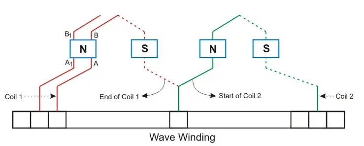
In a wave winding, we connect the end of one coil to the start of another coil of the same polarity. The coil side (A – B) progresses forward around the armature to another coil side and goes on successively passing through North and South poles until it returns to a conductor (A1-B1) lying under the starting pole.


This winding forms a wave with its coil, that’s why we call it a wave winding. Since we connect the coils in series, it is also referred to as a series winding. A diagram of a wave winding configuration is shown below.

图片6.png

Wave windings can be further classified into:


Simplex wave windings

Duplex wave windings

Retrogressive wave windings

Progressive wave windings


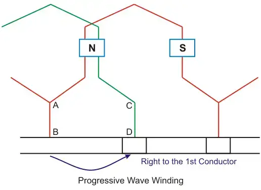
Progressive Wave Winding


If, after one round of the armature, the coil falls into a slot to the right of its starting slot, it is called progressive wave winding.

图片7.png

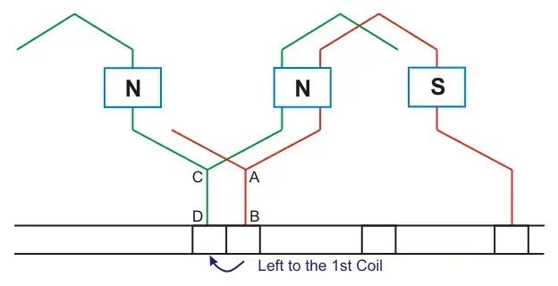
Retrogressive Wave Winding


If, after one round of the armature, the coil falls into a slot to the left of its starting slot, it is called retrogressive wave winding.

图片8.png

Here in the picture above we can see that 2nd conductor CD is in the left of the 1st conductor.


Important Points about Simplex Wave Winding

图片9.png


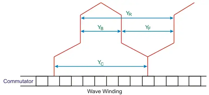
In simplex wave winding, the back pitch (YB) and front pitch (YF) are both odd and have the same sign.


The back-pitch and front-pitch are nearly equal to the pole pitch and maybe equal or differ by ±2. + for progressive winding, – for retrogressive winding.

图片10.gif


Here, Z is the no of conductors in the winding. P is the no of poles.


Average pitch (YA) must be an integer number, because it may close itself.


We take ± 2 (two) because after one round of the armature the winding falls sort of two conductors.


If we take an average pitch Z/P then after one round the winding will close itself without including all coil sides.


Since average pitch must be an integer, this winding is not possible with any no. of conductors.


Let us take 8 conductors in a 4 pole machine.

图片11.png


Being fractional no the wave winding is no possible but if there was 6 conductors then the winding can be done. Since,

图片12.png


For this problem the DUMMY COILS are introduced.


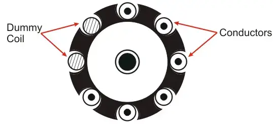
Dummy Coil

Wave winding is only possible with specific numbers of conductors and slot combinations. Standard stampings in the winding shop might not always match the design requirements, so dummy coils are used in such cases.


These dummy coils are placed in the slots to give the machine the mechanical balance but they are not electrically connected to the rest of the winding.

图片13.png


In multiplex wave winding:

图片14_WH_300x15px.jpg


Where:


m is the multiplicity of the winding

m = 1 for simplex winding

m = 2 for duplex winding

图片16.gif


Construction of Wave Windings


Let us develop a simplex and progressive wave winding diagram of a machine having 34 conductors in 17 slots and 4 poles.


Average pitch:

图片17.gif


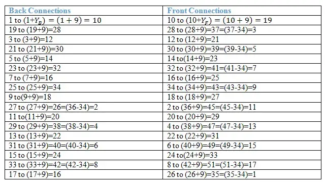
Now we have to construct a table for the connection diagram:

图片18.png


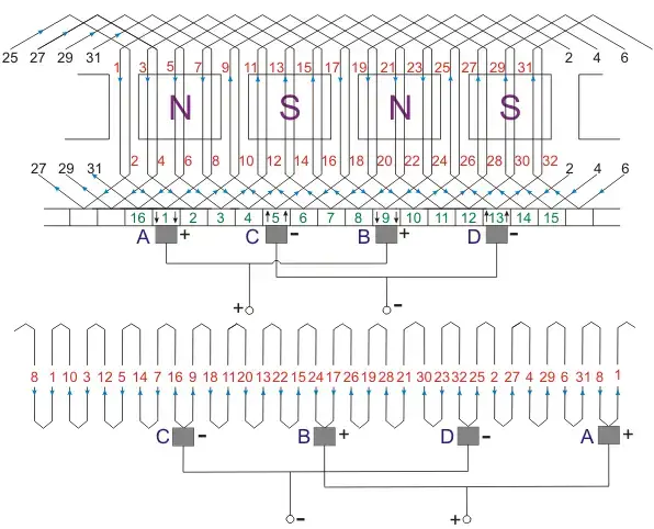
Wave Winding Diagram

图片19.png

Simplex Wave Winding Advantages

The advantages of simplex wave windings include:


In this winding, only two brushes are required but more parallel brushes can be added to make it equal to the no. of poles. If one or more brushes set poor contacts with the commutator, satisfactory operation is still possible.


This winding gives sparkles commutation. The reason behind that it has two parallel paths irrespective of the number of poles of the machine. The conductors in each of the two parallel paths distributed around the armature in the entire circumference.


No. of conductors in each path = Z/2, Z is the total no. of conductors.


Generated emf = average emf induced in each path X Z/2


For a given number of poles and armature conductors, it gives more emf than that of lap winding. Hence wave winding is used in high voltage and low current machines. This winding is suitable for small generators circuit with a voltage rating of 500-600V.


Current flowing through each conductor.

图片20_WH_350x39px.jpg

Ia is the armature current. The current per path for this kind of winding must not be exceeded 250A.


The resultant emf around the entire circuit is zero.


Simplex Wave Winding Disdvantages


The disadvantages of simplex wave windings include:


Wave winding cannot be used in machines having higher current rating because it has only two parallel paths.


Wenzhou Rockwell Transformer Co., Ltd. It is a high - tech enterprise integrating R & D, production, sales, and service. It focuses on the manufacturing of power transformers and supporting equipment, and is committed to providing efficient, reliable, and energy - saving power transmission and distribution solutions for global customers. We can offer: •Distribution transformers and substations •Outdoor switchgears and breakers(recloser) •Switchgears and it’s components (GIS, RMU, VCB, SF6 CB) Market and Service: We always take customers as the orientation and provide customized services according to their requirements. Our products are exported to the Middle East, Africa, Northern Europe, South America, and many other countries and regions. Drive the future of electricity with technological innovation and become a leading global supplier of intelligent power equipment.

What factors need to be considered when designing a transformer?
Transformer design is a complex process that requires consideration of multiple factors to ensure safe and efficient operation. In addition, compliance with international and local regulations is essential to guarantee that transformers meet safety and performance standards. Below are key factors to consider in transformer design and the relevant regulations to follow:Transformer Design Factors: Voltage and Frequency: Determine the input and output voltage levels and the operating frequency. The
Vziman
09/02/2025
What failure modes are possible in a transformer? How to identify and fix these failures?
Transformers are critical components in power systems, and various failure modes can affect their operation. Timely identification and resolution of these failure modes are essential to prevent costly downtime and ensure system reliability. Below are some common transformer failure modes, along with methods to identify and address them: Insulation FailureIdentification: Insulation failure leads to decreased insulation resistance, which can be detected through insulation resistance testing (megge
09/02/2025
Fault Analysis and Treatment of Oil-Immersed Transformers
Oil Leakage at Welded JointsOil leakage at welded joints primarily stems from poor welding quality, such as incomplete or detached welds, and defects like pinholes and gas pores. Although oil-immersed transformers are initially coated with solder and paint during manufacturing, potentially masking these issues temporarily, the defects tend to surface during operation. Additionally, electromagnetic vibration can cause weld cracks, leading to oil leakage.To resolve such leaks, the first critical s
08/29/2025
What losses occur during operation of the transformer? How to reduce losses?
Transformers experience various types of losses during operation, primarily categorized into two main types: copper losses and iron losses.Copper LossesCopper losses, also known as I²R losses, are caused by the electrical resistance of the transformer windings—typically made of copper. As current flows through the windings, energy is dissipated in the form of heat. These losses are proportional to the square of the load current (I²R), meaning they increase significantly with high
Rockwell
08/29/2025
Inquiry
Download
IEE-Business is dedicated to serving the personnel in the global power industry.
Join IEE-Business, not only can you discover power equipment and power knowledge, but also canhnd like - minded friends!