he foundation design of prefabricated substations is a critical interface between electrical and civil engineering, directly affecting equipment installation accuracy, operational safety, and service life. In this article, “prefabricated substation” covers box-type substations, prefabricated cabins, and modular substations. It summarizes key design points and a review checklist from four aspects: drainage slope, embedded channel steel, cable trenches, and settlement control.
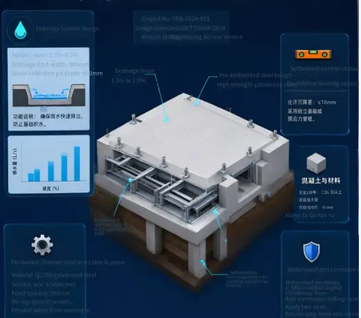
1. Drainage Slope: Prevent Backflow First, Then Organize Discharge
Water accumulation is one of the most common hazards for prefabricated substation foundations. Rainwater infiltrating through cable openings, the bottom of the enclosure, or foundation gaps can cause equipment moisture, grounding corrosion, and reduced cable insulation.
Design Points:
- The top of the foundation should be 300–500 mm above the outdoor ground level. In areas with high groundwater, low-lying terrain, or heavy rainfall, it should be raised to 600 mm or more.
- A drainage slope of 3%–5% should be provided around the foundation to allow rainwater to drain quickly from the top surface.
- The internal floor slab should slope toward a sump pit or drainage outlet with a minimum slope of 0.5%. Cable entry points should slope outward to prevent rainwater backflow along cable conduits.
- Weather-resistant sealant, mortar sealing, or curved edging should be installed between the box-type substation foundation and the prefabricated cabin base to prevent rainwater infiltration along contact joints.
- A sump pit or drainage hole should be provided within the foundation, with a submersible pump connected to the station drainage system if necessary.
- Waterproof sleeves should be provided for wall-penetrating conduits and cable entry/exit points, with fireproof and waterproof sealing completed after installation.
Note: The drainage slope around the top of a box-type substation foundation is typically controlled at 3%–5%. The cable trench bottom drainage generally slopes toward the sump pit at no less than 0.5%. Drainage slopes are typical engineering practice values and shall be confirmed by the civil design and local drainage requirements.
2. Embedded Channel Steel: Precision Determines Equipment Installation Quality
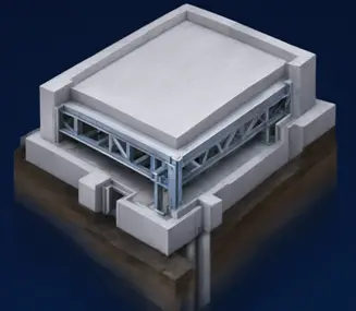
Embedded channel steel, also called foundation channel steel, serves equipment fixing, leveling, and grounding connections. Uneven or misaligned channel steel can cause cabinet deformation, busbar stress, handcart jamming, poor contact, and in severe cases, overheating or short circuits.
Design Points:
- Channel steel positions must align with equipment base flange holes and cabinet mounting holes. Verify against the manufacturer's foundation drawings before embedding.
- The top surface of channel steel should be level, with flatness deviation generally controlled within no more than 1 mm per meter and 5 mm over the full length.
- Position deviation of embedded bolts or channel steel should not exceed 5–10 mm. Bolt protrusion height should be 50–80 mm, matching the equipment base.
- Channel steel must be reliably grounded, typically using hot-dip galvanized flat steel connected to the foundation grounding grid. Grounding resistance is generally required to be no more than 4 Ω for typical low-voltage and distribution-level protective earthing. The final value shall comply with the applicable grounding standard, such as IEC 61936-1:2021 or IEC 62271-202:2022, or local project requirements.
- Channel steel should be prefabricated into an integral frame during processing and treated for corrosion resistance to minimize on-site welding deformation.
- Secure firmly before concrete pouring to prevent displacement during vibration and pouring. Recheck elevation, flatness, and relative positions after pouring.
For prefabricated foundations, channel steel, grounding flat steel, lifting rings, fence embeds, and cable conduits should be integrally embedded at the factory stage to reduce structural damage from on-site core drilling and supplementary embeds.
3. Cable Trench: Capacity, Drainage, Waterproofing, and Fireproofing Must Be Reserved in Advance
Prefabricated substation foundations typically form entry and exit pathways together with cable trenches and conduits. Cable trench design should not only consider cable accommodation, but also address laying, maintenance, drainage, fireproofing, and future expansion.
Design Points:
- Determine the number of cable circuits, voltage levels, cable outer diameters, and bending radii first, then determine trench width, depth, and bracket tiers.
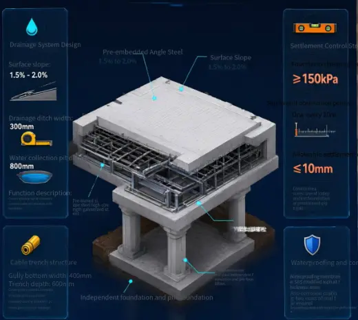
- The reserved cable trench width within the box-type substation foundation can be 300–500 mm, with a depth of no less than 600 mm. Specific dimensions should be verified based on cable quantity, bracket layout, and maintenance requirements.
- The lowest cable tier should be no less than 100 mm above the trench bottom. The top tier should meet bending radius and maintenance clearance requirements from the cover plate.
- Cable trenches should have a longitudinal drainage slope, generally no less than 5‰, and no less than 3‰ in difficult sections, sloping toward the sump pit or drainage system.
- Brackets and exposed steel components within the trench should be hot-dip galvanized or reliably treated for corrosion resistance. Cover plates should meet pedestrian or vehicular load requirements.
- Cables of different voltage levels should be laid in separate tiers. Power and control cables, as well as strong and weak current cables, should be separated or isolated.
- Fireproof and waterproof sealing should be provided at wall penetrations and foundation entry/exit points to prevent rainwater, small animals, and moisture ingress.
During prefabricated cable trench assembly, joint sealing, foundation treatment, and drainage slope should be strictly controlled to prevent trench cracking, step-offs, or water accumulation caused by foundation settlement.
4. Settlement Control: Closed-Loop Management from Geotechnical Investigation to Monitoring
Uneven settlement of prefabricated substation foundations can cause enclosure tilting, channel steel deformation, cable stress, loose grounding connections, and even compromise equipment safety.
Design Points:
- Conduct a geotechnical investigation first. Key parameters include bearing capacity, soft soil layers, groundwater level, frost heave potential, and backfill conditions. Foundation bearing capacity should generally be no less than 150 kPa, subject to geotechnical investigation and local structural design standards.
- Select the foundation type based on equipment weight, vibration characteristics, and geotechnical conditions. Options include reinforced concrete raft foundations, strip foundations, pile foundations, or prefabricated modular foundations.
- Concrete strength class should generally be no less than C25/30 or an equivalent local grade. Heavy-duty or large box-type substations should use C30/37 or an equivalent grade. Frost resistance should be considered in cold regions, and impermeability in humid or high-groundwater areas.
- A double-layer, two-way reinforcement mesh should be provided at the foundation base, with a concrete cover thickness of no less than 40 mm. Expansion joints or post-cast strips should be provided for longer foundations.
- Prefabricated foundation assembly joints should include reliable connection details such as post-cast strips, shear keys, leveling devices, and bolted connections to ensure overall stiffness and settlement compatibility.
- Backfill should be compacted in layers to prevent voids, subsidence, and rainwater infiltration around the foundation.
- Settlement monitoring points should be established after commissioning, with periodic re-measurement of foundation elevation, flatness, and enclosure verticality. Uneven settlement should be promptly analyzed and addressed through reinforcement measures. For foundations already in service, remedial methods such as grouting lifting or local reinforcement may be adopted depending on the severity of settlement.
5. Design Review Checklist
| Discipline |
Review Focus |
Typical Control Values |
| Elevation and Drainage |
Foundation top elevation, perimeter drainage slope, internal slope |
300–500 mm above ground; 3%–5% perimeter; trench bottom ≥0.5% |
| Embedded Channel Steel |
Position, flatness, fixing method, corrosion protection |
Flatness ≤1 mm/m, ≤5 mm full length; deviation ≤5–10 mm |
| Cable Trench |
Cross-section dimensions, brackets, drainage, sealing |
Width 300–500 mm, depth ≥600 mm; longitudinal slope ≥5‰ |
| Grounding |
Grounding flat steel, grounding terminals, resistance |
Grounding resistance generally ≤4 Ω |
| Settlement |
Bearing capacity, reinforcement, assembly joints |
Bearing capacity ≥150 kPa; post-cast strips or shear keys as needed |
In actual projects, prefabricated substation foundation design should be based on the equipment manufacturer's installation drawings, foundation load drawings, and site geotechnical reports, with coordinated review across electrical, civil, drainage, and fire protection disciplines. In particular, embedded channel steel positions, cable trench outlet elevations, and drainage slopes must be confirmed before pouring or prefabrication to avoid late-stage core drilling, rework, and settlement risks.
Note: The parameters in this article are common engineering practice values. Grounding resistance of ≤4 Ω is typical for many protective earthing applications under IEC-based systems, but the final design shall be verified against equipment manufacturer drawings, geotechnical reports, and applicable standards such as IEC 62271-202:2022, IEC 61936-1:2021, and local project requirements. Drainage slopes, channel steel tolerances, and bearing capacity values should also be confirmed by the relevant civil, structural, and grounding design requirements.









 Login