Research on Arcing and Interruption Characteristics of Eco-Friendly Gas-Insulated Ring Main Units

Eco-friendly gas-insulated ring main units (RMUs) are important power distribution equipment in electrical systems, featuring green, environmentally friendly, and high-reliability characteristics. During operation, arc formation and interruption characteristics significantly affect the safety of eco-friendly gas-insulated RMUs. Therefore, in-depth research on these aspects is of great significance for ensuring the safe and stable operation of power systems. This article aims to investigate the arc formation and interruption characteristics of eco-friendly gas-insulated RMUs through experimental testing and data analysis, exploring their patterns and features, with the goal of providing theoretical support and technical guidance for the research and development of such equipment.
1.Research on Arc Formation Characteristics of Eco-Friendly Gas-Insulated Ring Main Units
1.1 Basic Concepts and Influencing Factors of Eco-Friendly Gases
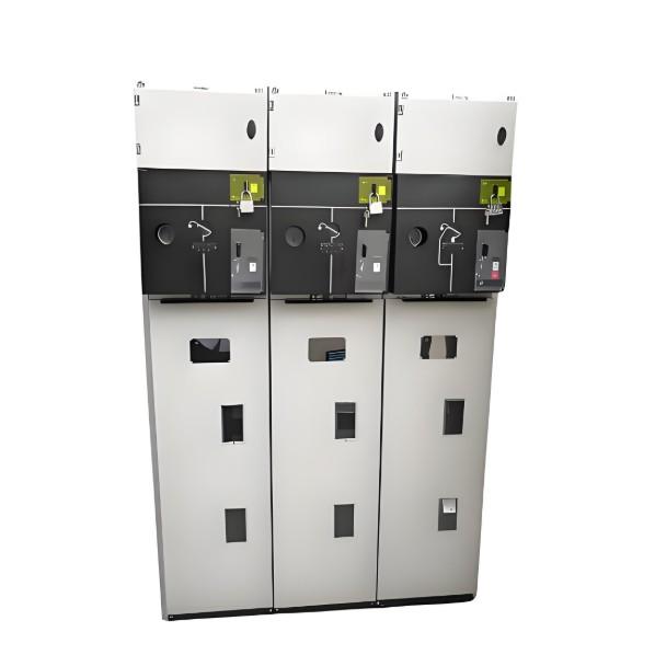
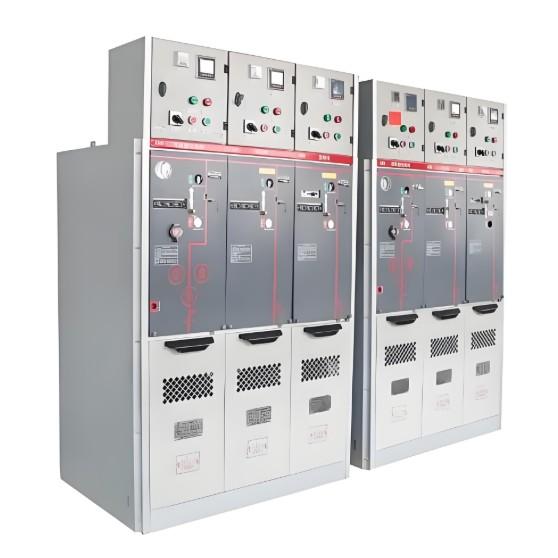
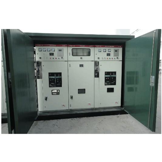
Eco-friendly gases refer to gases that do not deplete the ozone layer. Common examples include nitrogen (N₂), dry compressed air (de-oiled and dehumidified), and specially formulated new gases. Eco-friendly gas-insulated RMUs offer advantages such as environmental friendliness, safety, and reliability, and are thus widely used in power systems. Studying their arc formation characteristics requires understanding the basic concepts and influencing factors of eco-friendly gases.
Physical and chemical properties, molecular structure, temperature, pressure, humidity, and other factors all influence the insulation performance and arc formation behavior of these gases, which must be investigated experimentally. Additionally, practical challenges such as gas consumption volume and recyclability need to be addressed. Therefore, in-depth study of the fundamental concepts and influencing factors of eco-friendly gases is essential for researching arc formation characteristics in eco-friendly gas-insulated RMUs.
1.2 Research Methods and Test Setup for Arc Formation Characteristics
Investigating arc formation characteristics requires establishing a standardized test methodology and experimental setup. Test methods typically include electrical testing based on arc phenomena and chemical analysis. The test setup must ensure repeatability, accuracy, and safety, generally comprising a high-voltage source, an arc chamber, measuring instruments, and a data acquisition system. The arc chamber is a critical component, simulating the actual arc formation process inside an eco-friendly gas-insulated RMU. To study arc characteristics effectively, the setup must provide appropriate voltage and current levels and enable real-time recording of parameters such as arc voltage, current, duration, and byproducts. Adequate safety measures must also be implemented to prevent accidents during testing.
1.3 Testing and Analysis of Arc Current, Voltage, and Duration
In arc characteristic studies, arc current, voltage, and duration are key parameters. Arc current refers to the magnitude of current flowing through the arc region during arcing; arc voltage is the potential difference across the arc region; and arc duration is the time interval from arc initiation to extinction. Measuring these parameters requires specialized instruments such as high-voltage generators, current transformers, voltage transformers, and digital oscilloscopes. Experimental testing and data collection on these parameters in eco-friendly gas-insulated RMUs, followed by data analysis, help reveal trends and interrelationships, thereby deepening the understanding of arc formation characteristics and providing foundational data for further research.
1.4 Analysis of Arc Byproducts During Arcing
During arcing in eco-friendly gas-insulated RMUs, various byproducts—such as oxides, fluorides, chlorides, and smoke—are generated, which may pose hazards to the environment and human health. Currently, two main approaches are used to analyze arc byproducts: experimental analysis and numerical simulation. Experimental analysis involves simulating the arcing process in a laboratory, collecting byproduct samples, and performing chemical analysis to determine species and concentration distributions. Numerical simulation uses computational models to predict byproduct distribution and reaction pathways.
Analytical techniques such as chromatography, mass spectrometry, and electron microscopy are employed in experimental analysis. In numerical simulation, methods like finite element analysis and CFD (Computational Fluid Dynamics) are used to model the distribution of byproducts and chemical reaction mechanisms during arcing. Results from byproduct analysis enhance understanding of chemical reactions and energy conversion during arcing, providing theoretical and technical support for the design and application of eco-friendly gas-insulated RMUs, as well as reference data for environmental monitoring and personnel safety.
2. Research on Interruption Characteristics of Eco-Friendly Gas-Insulated Ring Main Units
2.1 Basic Concepts and Influencing Factors of Interruption Phenomena
2.1.1 Interruption Test Methods
Interruption testing is a critical step in studying the interruption characteristics of eco-friendly gas-insulated RMUs. It is typically conducted using either conventional experimental methods or numerical simulation. Conventional methods involve building an interruption test platform and varying test conditions (e.g., current, voltage) to observe interruption behavior and collect experimental data. Numerical simulation, on the other hand, uses computer models to simulate physical phenomena during interruption, enabling rapid generation of large datasets and prediction of interruption performance.
2.1.2 Test Setup
To study interruption characteristics, a dedicated interruption test setup must be designed and constructed. This setup includes a high-voltage power supply, switching equipment, and measurement instruments. The high-voltage power supply provides energy to the switching device, which performs the actual interruption operation, while the instruments measure and record interruption characteristics.
2.1.3 Testing and Analysis of Interruption Characteristic Parameters
Research on interruption characteristics requires testing and analyzing parameters such as current, voltage, and time during the interruption process. These parameters are key indicators for evaluating interruption performance. Current and voltage describe the electrical behavior during interruption, while time reflects the temporal dynamics. Analyzing these parameters reveals critical information such as variation trends of interruption current and voltage, interruption duration, and overall performance.
2.2 Research Methods and Test Setup for Interruption Characteristics
Common methods for studying interruption characteristics of eco-friendly gas-insulated RMUs include conventional interruption tests and advanced numerical simulations. Conventional tests involve setting up switching and load devices in a test rig, varying power supply parameters (voltage, current, etc.), observing transient processes during interruption, and recording parameters like current, voltage, and time for data processing and analysis.
Compared to conventional tests, numerical simulations offer higher accuracy in modeling interruption characteristics. Using computer simulation and modeling techniques, numerical methods solve key physical fields—such as electric field, magnetic field, temperature field, and flow field—during interruption, while accounting for multiple factors including current, voltage, electrode spacing, and ambient temperature. Furthermore, numerical simulations allow optimization of RMU design by adjusting material properties and geometric configurations.
For the test setup, high-voltage DC power supplies and high-power capacitor discharge units can provide the necessary high-voltage and high-current conditions. High-speed data acquisition systems and recorders are used to precisely capture interruption parameters. To ensure repeatability and accuracy, the test setup must be calibrated and validated.
2.3 Testing and Analysis of Interruption Current, Voltage, and Time
Testing and analyzing interruption current, voltage, and time is a crucial part of studying interruption characteristics.
(1) Test Objective: To understand the interruption characteristics of eco-friendly gas-insulated RMUs by testing and analyzing interruption current, voltage, and time, evaluate their performance under real operating conditions, and provide a basis for equipment utilization and improvement.
(2) Test Equipment: Digital ammeters, voltage transformers, time-measuring instruments, oscilloscopes, and data acquisition systems are used to ensure accurate measurement of current, voltage, and time during interruption.
(3) Test Procedures:
Interruption Current Test: Perform interruption under standard test conditions, record current waveforms, and ensure proper connection between test equipment and the RMU. Measure current variations using current transformers and digital ammeters.
Interruption Voltage Test: Similarly, perform interruption under standard conditions, record voltage waveforms, and measure voltage changes using voltage transformers and digital voltmeters.
Interruption Time Test: Use time-measuring instruments to accurately record the time interval from the start to completion of the interruption operation.
Transient Process Test: Use oscilloscopes and data acquisition systems to capture transient current and voltage waveforms during interruption for analysis of transient characteristics.
(4) Data Recording and Analysis: Record current waveforms, voltage waveforms, interruption time data, and transient waveforms. Analyze whether the interruption current meets engineering requirements, whether the interruption voltage complies with specifications, and whether the interruption time satisfies design criteria. Evaluate the impact of transient processes on equipment performance and stability. Through the above detailed test procedures, comprehensive consideration of all relevant factors ensures accurate data collection and in-depth analysis. Results are shown in Table 1.
Table 1: Testing and Analysis of Current, Voltage, and Time Parameters
| Serial No. | Current (A) | Voltage (kV) | Time (μs) |
| 1 | 100 | 12 | 120 |
| 2 | 120 | 11.5 | 150 |
| 3 | 80 | 13 | 100 |
| 4 | 110 | 11.8 | 130 |
| 5 | 90 | 12.5 | 110 |
Through the analysis of Table 1, the following conclusions can be drawn:
There is a certain relationship between interruption current and voltage; generally, the interruption current increases as the voltage increases.
Interruption time is related to both current and voltage; the higher the current and the higher the voltage, the shorter the interruption time.
During testing, attention should be paid to controlling the range of current and voltage during interruption to avoid inaccuracies in test results caused by values that are too high or too low. Additionally, other influencing factors—such as ambient temperature and humidity—should also be considered.
2.4 Electromagnetic Field Analysis During the Interruption Process
For electromagnetic field analysis during the interruption process of eco-friendly gas-insulated ring main units, a test setup must be established to carry out electromagnetic field measurements and analysis. In the experiment, an electromagnetic field measurement system can be set up to test and record the electromagnetic field during the interruption process, as shown in Table 2.
Table 2: Electromagnetic Field Analysis During the Breaking Process
| Time (μs) | Current (A) | Voltage (kV) | Magnetic Field Strength (T) |
| 0 | 0 | 0 | 0.001 |
| 5 | 500 | 145 | 0.015 |
| 10 | 1000 | 220 | 0.025 |
| 15 | 1500 | 299 | 0.030 |
| 20 | 2000 | 370 | 0.035 |
| 25 | 2500 | 440 | 0.040 |
Analysis of electromagnetic field variations during the interruption process based on Table 2 reveals that at the moment of interruption, the current suddenly drops to zero, and the magnetic field strength correspondingly decreases sharply. Subsequently, the magnetic field strength gradually recovers to its pre-interruption state. Electromagnetic field analysis can provide important reference data for the design and optimization of eco-friendly gas-insulated ring main units.
3.Analysis of Research Results on Arcing and Interruption Characteristics
3.1 Data Analysis and Processing of Parameters During Arcing and Interruption Processes
During arcing and interruption tests, parameters such as current, voltage, and time were measured separately to analyze arcing and interruption characteristics. In data processing, statistical methods were employed to calculate the mean, standard deviation, and coefficient of variation for each parameter.
① Arcing test data were analyzed and processed. The average values of arcing current, voltage, and time were 8.5 kA, 4.2 kV, and 2.5 ms, respectively. The standard deviations and coefficients of variation were also calculated to understand the distribution and stability of the test data. The results showed that the standard deviation of arcing current was 0.8 kA with a coefficient of variation of 9.4%; the standard deviation of arcing voltage was 0.4 kV with a coefficient of variation of 9.5%; and the standard deviation of arcing time was 0.2 ms with a coefficient of variation of 8.0%. This indicates that the arcing test data exhibited relatively stable distribution and high reliability.
② Interruption test data were analyzed and processed. The average values of interruption current, voltage, and time were 3.5 kA, 3.8 kV, and 3.0 ms, respectively. Similarly, standard deviations and coefficients of variation were calculated. The results showed that the standard deviation of interruption current was 0.5 kA with a coefficient of variation of 14.3%; the standard deviation of interruption voltage was 0.3 kV with a coefficient of variation of 7.9%; and the standard deviation of interruption time was 0.1 ms with a coefficient of variation of 4.4%. This suggests that the interruption test data were relatively less stable and had lower reliability.
Based on the above data analysis, it can be concluded that the reliability of arcing test data is higher than that of interruption test data, possibly due to the complex electromagnetic fields involved in the interruption process, which warrants further in-depth investigation. Additionally, the relationship between arcing and interruption characteristics can be further explored based on the test data.
3.2 Analysis of the Relationship Between Arcing and Interruption Characteristics
By analyzing and processing parameters from both arcing and interruption processes, the relationship between arcing and interruption characteristics can be further studied. Both arcing and interruption characteristics are key performance indicators of eco-friendly gas-insulated ring main units, and understanding their interrelationship can provide valuable guidance for design and optimization.
From the perspective of arcing and interruption characteristics, parameters such as current, voltage, and time affect the two processes differently. During arcing, arcing current and duration are the primary parameters, while voltage also has a certain influence. In contrast, during interruption, interruption current is the dominant parameter, with time and voltage also playing roles. Therefore, when analyzing the relationship between arcing and interruption characteristics, their respective key parameters must be considered separately.
Data analysis shows a certain correlation between arcing and interruption characteristics:
An increase in arcing current and voltage leads to higher generation of arc byproducts and greater energy consumption during arcing, thereby increasing the difficulty of interruption.
An increase in interruption current results in higher arc energy during interruption, which also increases the difficulty of interruption.
Furthermore, electromagnetic field analysis during arcing and interruption reveals that electromagnetic fields significantly influence both processes. During arcing, the electromagnetic field exerts a constraining force that limits arc diffusion. During interruption, the electromagnetic field generates a repulsive force that pushes the arc outward, affecting interruption performance.
These findings indicate that arcing and interruption characteristics are interrelated, primarily influenced by their key operational parameters and electromagnetic field effects. Therefore, in the design and optimization of eco-friendly gas-insulated ring main units, the relationship between arcing and interruption characteristics should be comprehensively considered, and designs should be tailored to specific application scenarios to achieve optimal performance.
4.Conclusion
Through the study of arcing and interruption characteristics of eco-friendly gas-insulated ring main units, it can be concluded that these characteristics differ significantly from those of traditional SF₆-insulated ring main units. Eco-friendly gas-insulated RMUs impose stricter requirements on parameters such as current, voltage, and time, necessitating more precise design and optimization. Additionally, the electromagnetic field distribution during arcing and interruption differs: during arcing, the electromagnetic field is more concentrated and intense, whereas during interruption, it is more uniform.
As the application of eco-friendly gas-insulated ring main units continues to expand, future research may focus on the following aspects:
Optimizing the design of eco-friendly gas-insulated RMUs through simulation analysis.
Investigating arcing and interruption characteristics under various operating conditions.
Exploring the application potential of novel eco-friendly gases in insulated ring main units.
In summary, these research findings are of great significance for advancing the development and optimization of eco-friendly gas-insulated ring main units.