How Input Voltage Affects the Current Through a Load Resistor in an Ideal Transformer
An ideal transformer is one that assumes no energy losses (such as copper loss or iron loss). Its primary function is to change the levels of voltage and current while ensuring that the input power equals the output power. The operation of an ideal transformer is based on the principle of electromagnetic induction, and there is a fixed turns ratio n between the primary and secondary coils, given by n=N2 /N1, where N1 is the number of turns in the primary coil, and N2 is the number of turns in the secondary coil.Impact of Input Voltage on Load Resistor Current When an input voltage V1 is applied to the primary coil of an ideal transformer, according to the turns ratio n, it induces a corresponding output voltage V2 in the secondary coil, which can be expressed by the following formula:
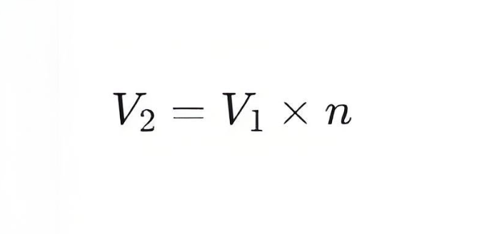
If the secondary coil is connected to a load resistor RL , then the current I2 flowing through this load resistor can be calculated using Ohm's Law:
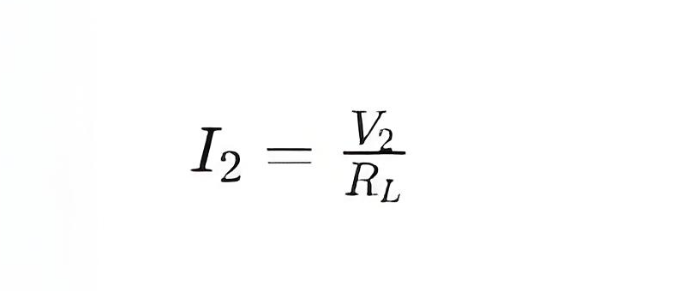
Substituting the expression for V2 into the above equation gives:
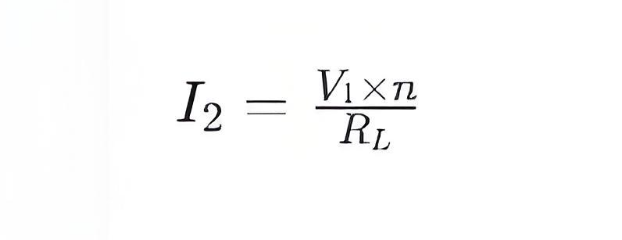
From this equation, it can be seen that for a given turns ratio n and load resistance RL, the secondary current I2 is directly proportional to the input voltage V1. This means:
When the input voltage V1 increases, if the turns ratio n and load resistance RL remain constant, the secondary current I2 will also increase accordingly.
When the input voltage V1 decreases, under the same conditions, the secondary current I2 will decrease.
It is important to note that in an ideal transformer, the input power P1 equals the output power P2, so:
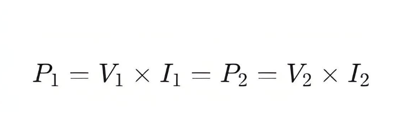
Here, I1 is the current in the primary coil. Since V2=V1×n, then I2=I1/n, indicating that the primary current
I1 is inversely proportional to the secondary current I2, both of which depend on the input voltage V1.
In summary, the input voltage V1 directly influences the current I2 flowing through the load resistor RL in an ideal transformer, and this effect is realized through the transformer’s turns ratio n.

 Login