• Product
  • Suppliers
  • Manufacturers
  • Solutions
  • Free tools
  • Knowledges
  • Experts
  • Communities
Search


How Does Capacitor Bank Inrush Current Arise, What Hazards Does It Bring, and What Integrated Techniques Help Suppress It?

Rockwill
Field: Manufacturing
10Year<
China
 
Inrush current is the most common transient phenomenon during the switching of reactive power compensation equipment. Why does a capacitor bank produce a "bang" impact sound when switched in? Why do some capacitor banks frequently burn out contact tips?
The culprit behind both of these problems is inrush current. A thorough understanding of its mechanism and hazards, combined with appropriate measures, is essential for the safe operation of power grids and equipment.
iee-business

1. What Is the Mechanism of Capacitor Bank Inrush Current Generation?

The generation of capacitor bank inrush current is mainly related to the physical characteristics of capacitors and the operating state of the grid. The specific causes include:

Cause Description
Capacitor characteristics The voltage across a capacitor cannot change suddenly. At the instant of closing, because the capacitor is uncharged (or holds residual charge), its terminal voltage differs from the grid voltage, forcing the capacitor to charge or discharge rapidly and producing a momentary surge current. In other words, the greater the voltage difference, the more severe the inrush current.
Small circuit impedance At the first closing of the capacitor, the inrush current is limited only by the relatively small circuit impedance, making the circuit approximate a short-circuit condition momentarily and generating a large switching surge.
Discharge effect during bank accumulation When a new capacitor bank is switched in while banks are already in operation, the charged banks discharge into the new one. Because bank groups are closely located with small phase-to-phase inductance, this creates even more severe inrush current. This is the industry's so-called "back-to-back" energization scenario, with frequencies reaching several kilohertz— particularly harmful.
Closing phase and grid state Closing near the peak of the voltage waveform produces greater inrush current, whereas closing at the voltage zero-crossing produces less. In addition, high grid load, low voltage, or the presence of harmonics can aggravate the surge.

 2. Potential Hazards of Inrush Current

Large inrush current imposes multiple negative impacts on the power system:

Hazard Description
Shortened equipment life Frequent high-amplitude surges erode the metal contacts of breakers, creating irregular, uneven contact surfaces that distort the electric field and raise the probability of re-strike, markedly shortening switchgear service life.
Overvoltage and equipment damage Inrush current produces extremely high transient overvoltage across series iron-core reactors, which can puncture the reactor insulation. Meanwhile, the mechanical and thermal stress intensifies aging of capacitor elements and can even lead to burnout. In fact, the first closing surge current can reach 5–20 times the rated current, far beyond what one might expect.
Grid operation disturbance High-frequency, high-amplitude surge currents degrade power quality and interfere with the normal operation of other sensitive electrical equipment.

 3. The Relationship Between Inrush Current and Restrike

It is worth emphasizing that inrush current suppression and restrike suppression form two sides of the same capacitor switching protection. Inrush current occurs on the closing side, restrike on the opening side. Although the two appear independent, together they determine the overall service life of the switching device.

If inrush current is suppressed while restrike is ignored, the high overvoltage at interruption can still puncture the insulation; the reverse is equally true. Therefore, a complete switching protection scheme must address both dimensions.

iee-business

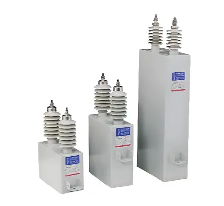
Three sizes of grey high voltage capacitor units with insulator terminals 

4. Main Methods for Limiting Inrush Current

The following methods are commonly used to limit inrush current to a safe range:

Method Description
Series reactor The most common and effective measure. Using the principle that inductive current cannot change suddenly, it limits both the magnitude and frequency of the surge while also suppressing harmonic amplification. Reactance ratio is the key parameter: 6% suppresses harmonics of 5th order and above, while 4.5%–5% balances filtering and surge limiting.
Zero-crossing switching Uses thyristors, hybrid switches, or synchronous switches to connect the capacitor at the voltage zero-crossing and disconnect at the current zero-crossing, eliminating surge current at the source.
Pre-charging and current-limiting resistor During closing, the capacitor is first pre-charged through a series resistor via auxiliary contacts; once the voltage is established, the main contacts take over. This effectively limits the surge.
Standard operation procedures Capacitors must be fully discharged before re-closing, and closing while energized is prohibited. Avoid frequent switching and operation during high-load or high-harmonic periods.
Synchronous switching technology Precisely controlling mechanical switch contacts to close at zero voltage enables surge-free energization, eliminating the fragile thyristor components, simplifying structure, and improving reliability. However, switching quality depends on controller accuracy and actuator consistency, so the closing phase must be checked periodically.
 

Frequent contactor burnout is not only caused by high surge magnitude, but also by the cumulative effect of repeated surge impact combined with opening restrike, which gradually erodes contact material. With the development of power electronic technology, modern intelligent capacitor banks increasingly adopt a "thyristor + mechanical switch" hybrid switching scheme.

The thyristor performs precise zero-crossing switching to eliminate surge current, while the mechanical switch handles steady-state conduction to reduce losses. The two complement each other, and this has become a new direction in the high-end reactive compensation market.

6. Summary

Capacitor bank inrush current is mainly a transient large current caused by the fact that capacitor voltage cannot change suddenly and by the small circuit impedance. To ensure system safety, the most fundamental mitigation is the series reactor, supplemented by zero-crossing switching or pre-charging, and strict adherence to full-discharge procedures after de-energization.

Through the comprehensive combination of "hardware limiting + technical control + standard operation," inrush current can be limited to a safe range, effectively extending equipment life and maintaining grid stability. Understanding the mechanism of these surges and the countermeasures is not only essential for equipment selection but also a foundation of safe power system operation and maintenance.

Edited From: Garca

Give a tip and encourage the author!
Topics:

Comments

Share your question or perspective
WhatsApp
Send inquiry
+86
Click to upload file
Download
Get the IEE Business Application
Use the IEE-Business app to find equipment, obtain solutions, connect with experts, and participate in industry collaboration anytime, anywhere—fully supporting the development of your power projects and business.
Login
or continue with
New here?
Register