High-Voltage Power Transformer Winding: Advantages of Radial "Zero-Gap" Design

Radial zero-clearance winding, electric field smoothing, PD control, short-circuit durability, axial cooling, transformer efficiency

Vziman
Field: Manufacturing
10Year<
China
Add us on Google

Radial "zero-gap" design refers to the process of eliminating or drastically compressing the insulation spacer clearances between high-voltage winding discs (segments) in the radial direction, so that the discs are tightly fitted or closely stacked with minimal insulation material. Its core advantages are reflected in the following dimensions:

1. Electric Field Distribution Optimization

By eliminating air/oil gaps between winding discs, the radial electric field transitions from "non-uniform" to near "uniform," avoiding field strength distortion at the gaps. Specific effects include:
  • Significant increase in Partial Discharge Inception Voltage (PDIV)
  • Suppression of creepage hazards at the interface between insulation board and oil
  • Easier compliance with the partial discharge measurement requirements specified in GB 1094.3 / IEC 60076-3

https://www.vziman.com/Products/detail/three-winding-oil-immersed-power-transformer-for-power-plant-220kv-2860

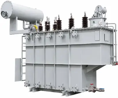
Vziman SF11 Series Three-Winding Oil-Immersed Power Transformer

2. Heat Dissipation and Thermal Stability

  • Conventional design: Disc → Oil duct (spacer clearances) → Disc
  • Zero-gap design: Discs tightly fitted, relying on axial oil ducts for concentrated heat transfer

Benefits:

  • Reduced radial temperature difference; hot-spot location becomes more predictable and controllable
  • Under forced oil circulation (OFAF/ODAF), axial oil flow is more concentrated, enhancing heat transfer efficiency
  • More uniform overall winding temperature distribution, extending insulation life (insulation life follows the Montsinger Rule: for every 6°C reduction in temperature, the insulation life approximately doubles)

3. Mechanical Strength and Short-Circuit Withstand Capability

This represents the most prominent engineering advantage of zero-gap design:

Parameter Conventional Design (with gaps) Radial Zero-Gap Design
Friction between discs Low (point contact via spacers) High (surface contact, integral structure)
Axial force distribution under short circuit Concentrated at spacer points Uniformly distributed across the entire winding surface
Risk of disc displacement Relatively high Extremely low
Resistance to cumulative deformation Moderate Excellent
 

The axial electrodynamic forces generated during short-circuit conditions can reach dozens of times the winding weight. Zero-gap design enables the discs to form an integral rigid structure, substantially enhancing sudden short-circuit withstand capability (in compliance with IEC 60076-5 short-circuit withstand testing requirements).

4. Insulation Reliability and Service Life

  • Elimination of gaps means elimination of bubble-trapping sites—the primary cause of partial discharge
  • During impregnation processes (VPI/VPC), resin fills more thoroughly with no residual cavities
  • During operation, the insulation aging path remains singular, with no localized degradation at gap positions

5. Structural Compactness

  • For the same capacity, the axial height of the winding can be reduced, and the core window height can be correspondingly decreased
  • Effectively reduces core and coil weight as well as material costs (less silicon steel and copper conductor)
  • For extra-high/ultra-high voltage (≥220 kV) transformers, compact structure translates directly into economic benefits in terms of transport dimensions and weight

Application Scenarios and Design Considerations

Best Suited For: High-voltage / extra-high voltage windings of 110 kV and above power transformers, and large-capacity autotransformers.

Design Trade-offs:

  • Radial heat dissipation relies on axial oil duct design, requiring meticulous calculation of oil flow resistance
  • If electrical isolation between winding discs is required, extremely thin insulation paper (e.g., 0.05–0.13 mm cable paper) must be used, demanding exceptionally high winding precision
  • Not suitable for on-load tap-changing winding sections that require frequent turns adjustment

Vziman Three-Winding Transformer Integration

The Vziman three-winding transformer systematically addresses the core technical challenges in high-voltage winding design through three key innovations: a zigzag oil guide structure for optimized heat dissipation, a radial zero-gap compact winding process for insulation reliability, and independent voltage-regulating windings that balance functional flexibility with structural stability. Together, these features deliver a robust, reliable, and long-service-life solution for 110 kV and above power systems.
Edited From:Echo


Give a tip and encourage the author!

Comments

Share your question or perspective
WhatsApp
Send inquiry
+86
Click to upload file
Download
Get the IEE Business Application
Use the IEE-Business app to find equipment, obtain solutions, connect with experts, and participate in industry collaboration anytime, anywhere—fully supporting the development of your power projects and business.
Login
or continue with
New here?
Register