What is Reactive Power Compensation Technology, Its Optimization Strategies, and Significance?

1 Overview of Reactive Power Compensation Technology
1.1 Role of Reactive Power Compensation Technology
Reactive power compensation technology is one of the widely used techniques in power systems and electrical grids. It is primarily employed to improve power factor, reduce line losses, enhance power quality, and increase the transmission capacity and stability of the grid. This ensures that power equipment operates in a more stable and reliable environment, while also boosting the grid’s ability to transmit active power.
1.2 Limitations of Reactive Power Compensation Technology
Although widely applied, reactive power compensation technology is not suitable for all application scenarios. For instance, in systems with frequently varying loads, the switching speed of compensation devices may fail to keep pace with rapid load changes. This can result in inadequate response, leading to unstable voltage fluctuations in the grid.
In certain cases, reactive power compensation equipment may generate harmonic currents and harmonic voltages, which can adversely affect the overall power system and connected equipment. Therefore, harmonic issues must be fully considered during the design and implementation of compensation schemes, and appropriate suppression measures should be adopted.
2 Optimization Strategies for Reactive Power Compensation
The reactive power compensation technology based on power capacitors proposed in this paper is implemented within a complete compensation system. The system mainly consists of three components: the S751e-JP main controller, the S751e-VAR control board (capacitor switching execution unit), and the power capacitor bank. Among these, the S751e-JP main controller and the S751e-VAR control board operate in a master-slave relationship.
During normal operation, the S751e-VAR control board receives instructions from the S751e-JP main controller and controls the internal composite switches accordingly to switch pre-grouped power capacitors. The S751e-JP main controller is responsible for collecting and analyzing real-time operational data from the power system. Using built-in software and algorithms, it calculates the required amount of reactive power compensation, then converts this information into signals compatible with the S751e-VAR control board. Upon receiving the command, the control board executes the switching operations according to preset logic, enabling precise reactive power compensation for the power system.
2.1 Design and Configuration of Reactive Power Compensation Equipment
2.1.1 Compensation Capacity of Power Capacitors
A simplified calculation method is commonly used to estimate the compensation capacity of power capacitors. However, this method has certain limitations in practical applications. Therefore, this paper adopts a more detailed and accurate algorithm to determine the required compensation. First, the initial power factor (cosφ) of the system under un-compensated conditions is established.
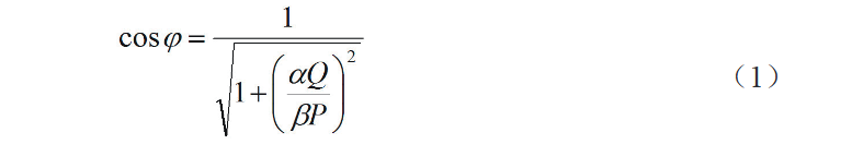
and are the active and reactive power values, respectively, when the grid is operating at full load;
is the annual average active load factor of the power system (or grid), typically ranging from 0.70 to 0.75;
is the annual average reactive load factor of the power system (or grid), generally taken as 0.76.
If the power system is already in normal operation, historical electricity consumption data can be used for calculation. In this case:
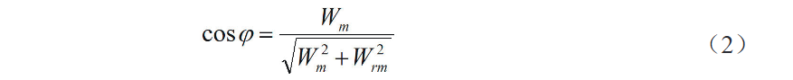
where:
Wm is the monthly average active energy consumption of the power system;
Wrm is the monthly average reactive energy consumption of the power system.
Based on the target power factor mentioned above, the actual compensation capacity of the power capacitor can be determined using the following formula:

2.1.2 Connection Methods of Power Capacitor Banks
During normal operation of the power system, power capacitor banks typically employ two basic connection methods: delta (Δ) connection and Y (wye) connection. Additionally, depending on the location of switching devices within the circuit, they can also be classified as internal or external switching configurations.
The delta connection enables fast, simultaneous three-phase compensation, effectively reducing the duration of line imbalance and improving compensation efficiency. However, it is generally suitable only for systems with relatively balanced three-phase loads and cannot achieve precise grid compensation.
The Y connection allows independent and accurate compensation for each phase of the capacitor bank. However, it may lead to under-voltage or over-voltage in one phase and typically involves higher implementation costs.
Therefore, this paper proposes a hybrid approach that combines the advantages of both connection methods, adjusting the number and capacity of capacitor groups according to actual load conditions.
2.1.3 Grouping Configuration of Power Capacitors
The grouping configuration of power capacitors generally includes equal-capacity and unequal-capacity schemes.
In equal-capacity grouping, the total capacitor bank is divided into groups of identical capacity, with the number of groups determined based on the total required capacity. This method offers simple assembly and straightforward switching control logic. However, due to fewer groups and larger individual capacities, it results in coarse compensation steps, making precise compensation difficult. Frequent switching may also accelerate equipment wear and increase maintenance costs.
In unequal-capacity grouping, capacitor capacities are distributed according to a predefined ratio (e.g., 1∶2∶4∶8). This approach provides higher compensation accuracy and flexibility, enabling fine-tuned reactive power regulation. However, it involves complex system design and control logic, limiting its scalability. Additionally, smaller-capacity capacitors may experience excessive switching operations, affecting long-term reliability.
After comprehensive evaluation, this paper adopts the equal-capacity grouping method. However, the capacity of the common compensation group is slightly larger than that of the split-phase compensation group. This configuration better supports cyclic switching operations, improves both compensation accuracy and response speed, and reduces control complexity. It also shortens the compensation cycle and enhances overall efficiency.
2.2 Optimization of Reactive Power Compensation Strategy
A well-designed reactive power compensation strategy ensures effective compensation under various operating conditions. During normal system operation, the real-time state of the compensation system can be divided into zones—such as the switching-in zone, stable zone, and switching-out zone—based on parameters like active and reactive power.
Optimizing the compensation strategy is a critical aspect of system design, directly influencing compensation performance. Traditional single-parameter control strategies focus only on one variable, making them inadequate for handling complex or dynamic conditions. This often leads to over-compensation or excessive switching, increasing operational and maintenance costs.
Therefore, this paper employs a multi-parameter composite control strategy. One parameter is used as the primary decision criterion, while several others serve as auxiliary factors. The system evaluates multiple parameters simultaneously, performs comprehensive calculations to determine switching requirements, and executes switching actions accordingly, improving control accuracy and stability.
2.3 Operation and Maintenance of Compensation Equipment
To enhance the stability and interference resistance of the compensation equipment, a built-in software protection system should be implemented. This ensures the device can operate normally or safely disconnect under various abnormal conditions, thereby improving operational reliability and safety.
Additionally, professional technicians should regularly conduct installation commissioning and inspections to identify potential safety hazards within the equipment and perform timely reinforcement.
Reactive power compensation systems are typically equipped with protective functions such as overcurrent, overvoltage, and undervoltage protection. To ensure these protections respond correctly to faults, regular testing of their operational performance is necessary. Furthermore, overcurrent and temperature protection should be implemented to detect abnormalities promptly and prevent fault escalation.