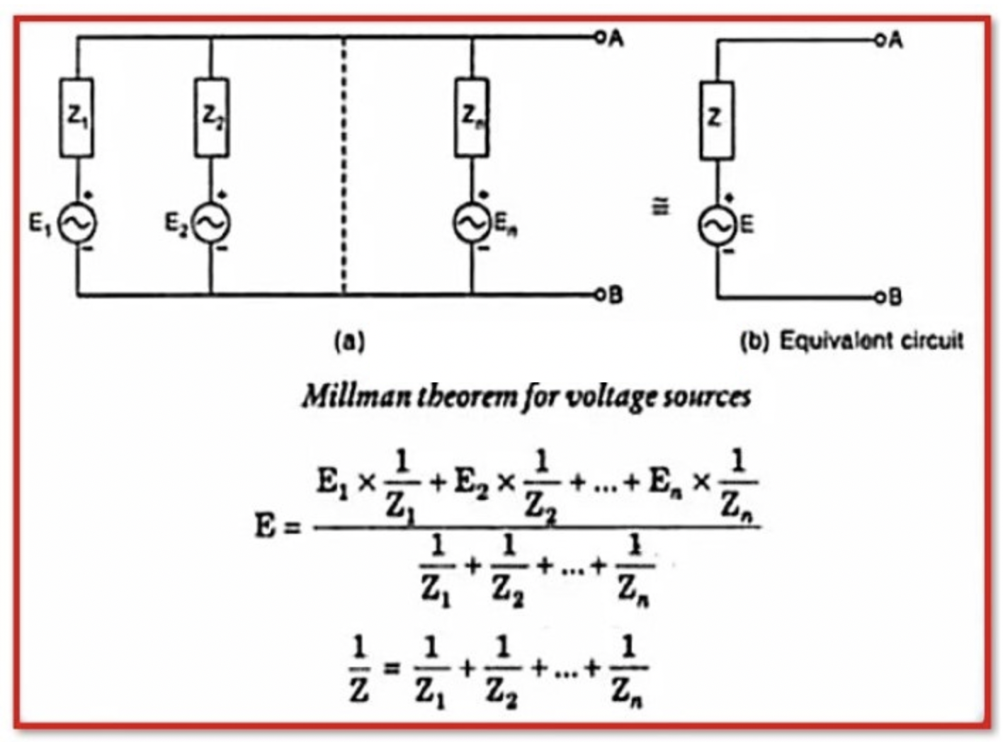
Millman’s Theorem

Rabert T
03/09/2024

Millman’s Theorem is a principle in electrical engineering that allows the complex impedance of a series of resistors and voltage sources to be reduced to a single equivalent impedance. It states that any series circuit consisting of a number of resistors and voltage sources can be represented by an equivalent circuit consisting of a single resistor in parallel with a single voltage source. The resistor is the equivalent resistance of the circuit, and the voltage of the source is the equivalent voltage of the circuit. Millman’s Theorem is named after the American engineer Jacob Millman, who first proposed it in the mid-20th century.

WechatIMG1353.png

To determine the equivalent resistance and voltage of a series circuit using Millman’s Theorem, the following steps can be followed:

  • Divide the circuit into a number of branches, each containing a single resistor and voltage source.

  • Calculate the equivalent resistance and voltage of each branch.

  • The equivalent resistance of the circuit is the sum of the individual branch resistances.

  • The equivalent voltage of the circuit is the sum of the individual branch voltages.

  • Millman’s Theorem is a useful tool for analyzing and designing series circuits because it allows the circuit to be represented by a single, simplified model. This makes it much easier to understand the behavior of the circuit and to calculate its response to different input signals.

Millman’s Theorem is only applicable to series circuits consisting of resistors and voltage sources. It is not applicable to circuits with other types of elements, such as inductors or capacitors. It is also not applicable to nonlinear circuits.

What is the outcome of Millman’s theorem?

It is an incredibly useful theorem for determining the voltage across the load and the current flowing through the load. It’s also known as the parallel generator theorem. A combination of voltage and current sources with parallel connections can be reduced to a single equivalent voltage (or) current source.

Millman’s Theorem Applications:

  • Millman’s theorem is particularly useful for determining the voltage and current of load impedance when a large number of parallel branches are available with a variety of voltage sources.

  • This theorem is simple to calculate. It does not necessitate the use of additional equations.

  • This theorem is used to solve complex circuits with complex elements such as Op-Amps.

Millman’s theorem Limitations:

  • This theorem does not apply to a circuit with a dependent source connected to an independent source.

  • This theorem is useless for circuits with less than two independent sources.

  • This theorem does not applicable to a circuit composed entirely of series parts.

  • This theorem is inapplicable when there is an element connected between the source and the destination.

Statement: Respect the original, good articles worth sharing, if there is infringement please contact delete.

Rabert T

As an electrical engineer with 5 years of experience, I focus on transformer and circuit breaker reliability in 110/33-11kV and 33/11kV substations. I am a professional electrical engineer with experience in transformer service and maintenance.

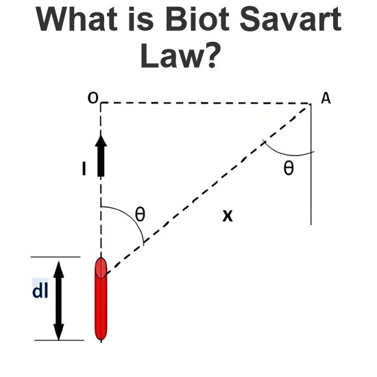
What is Biot Savart Law?
The Biot-Savart Law is employed to determine the magnetic field intensity dHnear a current-carrying conductor. In other words, it describes the relationship between the magnetic field intensity generated by a source current element. This law was formulated in 1820 by Jean-Baptiste Biot and Félix Savart. For a straight wire, the direction of the magnetic field adheres to the right-hand rule. The Biot-Savart Law is also referred to as Laplace’s law or Ampère’s law.Conside
Edwiin
05/20/2025
What is the formula for calculating current if voltage and power are known, but resistance or impedance is unknown?
For DC Circuits (Using Power and Voltage)In a direct - current (DC) circuit, the power P (in watts), voltage V (in volts), and current (in amperes) are related by the formula P=VIIf we know the power P and voltage V, we can calculate the current using the formula I=P/V. For example, if a DC device has a power rating of 100 watts and is connected to a 20- volt source, then the current I=100/20=5 amperese.In an alternating - current (AC) circuit, we deal with apparent power S (in volt - amperes),
Encyclopedia
10/04/2024
What are the validations of Ohm’s law?
Ohm's Law is a fundamental principle in electrical engineering and physics that describes the relationship between the current flowing through a conductor, the voltage across the conductor, and the resistance of the conductor. The law is expressed mathematically as:V=I×R V is the voltage across the conductor (measured in volts, V), I is the current flowing through the conductor (measured in amperes, A), R is the resistance of the conductor (measured in ohms, Ω).While Ohm's Law is widely accepted
Encyclopedia
09/30/2024
What is needed for a power supply to deliver more power in a circuit?
To increase the power delivered by a power supply in a circuit, you need to consider several factors and make appropriate adjustments. Power is defined as the rate at which work is done or energy is transferred, and it is given by the equation:P=VI P is power (measured in watts, W). V is voltage (measured in volts, V). I is current (measured in amperes, A).Thus, to deliver more power, you can either increase the voltage V or the current I, or both.Here are the steps and considerations involved:I
Encyclopedia
09/27/2024
Inquiry
Download
IEE-Business is dedicated to serving the personnel in the global power industry.
Join IEE-Business, not only can you discover power equipment and power knowledge, but also canhnd like - minded friends!