
AC (Alternating Current) bi DC (Direct Current) rectifier circuitê tayin de hatine.
Half-wave rectifiers,
Full-wave rectifiers, and
Bridge rectifiers
three basic kinds of rectifiers. All of these rectifiers have the same primary purpose, which is to convert current, however they do not do so effectively while doing so.
Both
The bridge rectifier and
The centre tapped full wave rectifier
are effective converters.

Electronic power sources have bridge rectifier circuits. In order to power the numerous electronic fundamental components from the available AC mains supply, many electronic circuits need a rectified DC power source. This rectifier is used in a broad range of electronic AC power devices, including
Welding applications,
Modulation processes,
Motor controllers, and
Residential appliances.
A summary of a bridge rectifier’s operation is covered in this post.
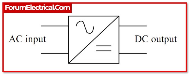
An alternator that converts mains AC input to direct current (DC) output is known as a bridge rectifier. Bridge rectifiers deliver DC voltage to electrical devices and components. Any other regulated solid-state switch (or) four (or) more diodes may be used to assemble them.
Load current determines the bridge rectifier.When selecting a rectifier power source for an appropriate purpose in an electrical system, factors like
Component ratings & specifications,
Breakdown voltage,
Temperature ranges,
Transient current rating,
Forward current rating,
Mounting requirements, and
others are taken into consideration.

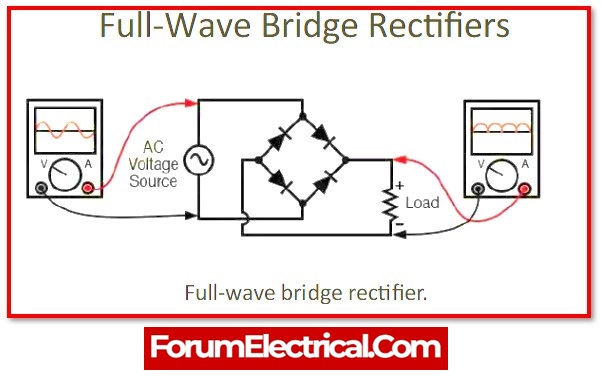
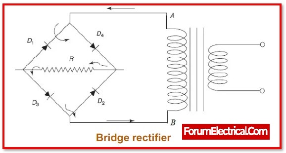
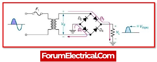
The four diodes D1, D2, D3, and D4 may be used in this circuit, alongside a load resistor (RL). To effectively convert AC to DC , these diodes may be connected in a closed-loop arrangement. This design’s key advantage is that it does not need a special center-tapped transformer. Thus, size and price will decrease.

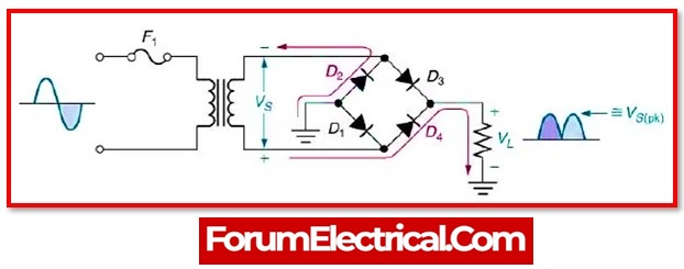
The output DC signal may be obtained across the RL after the input signal has been applied across two terminals, such as A & B. In this condition, a load resistor is attached between two terminals, C & D. The placement of two diodes may be done in such a manner that two diodes will conduct electricity during each half cycleD1 and D3 diode pairs will carry current during the positive (+) half cycle. D2 and D4 diodes conduct current during negative (-) half cycles.
A center-tapped transformer full-wave rectifier produces about half the output voltage of a bridge rectifier.Since it doesn’t require a center-tapped transformer, this circuit resembles a less cost rectifier.

The circuit diagram for a bridge rectifier includes many levels of components, including
Transformer,
Diode bridge,
Filtering, and
Regulators.
A regulated DC power supply is what all of these building blocks together are often referred to as, and it powers numerous electronic equipment.
A step-down transformer that modifies the input voltage’s amplitude makes up the circuit’s initial stage. The majority of electronic projects step-down the 230V AC mains supply to 12V AC supply using a 230/12V transformer.
Filtering is required to produce the output following the diode bridge rectifiers as a pure DC due to its pulsing nature. When the wave is smoothed, filtering is often carried out using one (or) more capacitors connected across the load. Output voltage impacts this capacitor rating.
The voltage regulator that keeps the output voltage constant is the final step of this controlled DC supply. The microcontroller runs at 5V DC, while the bridge rectifier outputs 16V. In order to lower this value and ensure that it remains constant irrespective of whether the input voltage varies, a voltage regulator is required.
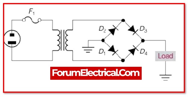
Four diodes comprise a single-phase bridge rectifier, which is linked across the load as previously explained.
D1 and D2 are forward biased in the Positive half cycle for the AC input waveform diodes, while D3 and D4 are reverse biased. The load current takes when the voltage rises over the diodes’ threshold levels and they start conduct.

The diodes D3 and D4 are biased forward in the negative half cycle for the AC input waveform, while D1 and D2 are biased backward. When the D3 & D4 diodes begin to conduct, load current begins to flow through them.

The load current flow of direction is the same in both condition making the current unidirectional and hence DC. Thus, the input AC current is changed into a DC current by using a bridge rectifier. This bridge wave rectifier


