Given the lack of manufacturers for such transformers on the market, we design them in - house. We provide technical specs to partners, specifying materials like high - temp enameled wires.
Electrical signals from downhole logging tools, transmitted via these transformers, impact formation - to - surface signal reliability. Thus, improving transformer consistency boosts signal uniformity, enhancing logging tool accuracy and our market competitiveness.
Our common signal transformers are EI - type, with cores of 40–80 μΩ·cm high - permeability permalloy, metal - shelled and silicone - potted. Transformer consistency depends on both design and manufacturing. For T1 transformers, low demand means manual production, causing quality issues. Past batches showed poor inductance consistency (±30% of central value, varying across batches), hindering circuit debugging and final product accuracy.
1 Analysis of Process Factors Affecting Consistency
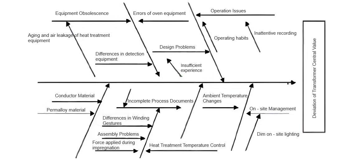
To address inconsistencies in transformer performance caused by manual operations and small - batch production, efforts must focus on process improvements. Transformer manufacturing spans multiple disciplines, with conductive, magnetic, and insulating materials having highly variable properties, making control challenging. Through market research and material data analysis, a cause - effect diagram for transformer center values and consistency is developed as follows:
1.1 Analysis of EI - type Transformer Manufacturing Process
Beyond general transformer process commonalities, the EI - type transformer’s unique characteristics require a comprehensive analysis of 14 terminal factors in Figure 1. Key factors impacting performance are:
Heat Treatment of Permalloy Materials: Lacking strict heat - treatment processes, small - batch production leads to experience - based operations for temperature control, core sheet alignment, and furnace vacuum. These factors critically affect impurity removal from alloy core surfaces and magnetic property enhancement (e.g., iron loss, permeability).
Material Magnetic Performance Variability: Domestic alloy materials have unstable properties. Permalloy batches show magnetic performance differences, reducing consistency.
Assembly Stress on Core Sheets: Uneven external stress during assembly degrades magnetic performance (typically >10% impact). Selecting flat core sheets and precise assembly improves consistency.
1.2 Process Improvement Measures
Based on these main causes of T1 transformer inductance inconsistency, targeted process improvements are implemented.
2 Process Improvement Measures and Implementation
2.1 Operators Strictly Control the Heat Treatment Process
Before heat treatment, arrange permalloy core sheets neatly and as flat as possible so that they do not bend after treatment, reducing stress during assembly. Meanwhile, check for burrs on core sheets after stamping before heat treatment. If burrs are severe, propose repair first before heat treatment.
Strictly follow the curve in Figure 2 for heat treatment. Raise the temperature uniformly for 3 hours until the furnace temperature reaches 1150°C, hold the temperature for 4 hours, then cool down to 400°C over 5 hours before taking the sheets out of the furnace.
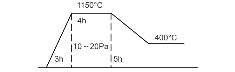
Strictly adhere to the original process requirements for vacuum pressure. Use an SG - 3 composite vacuum gauge to evacuate, achieving a vacuum degree of 10 - 20 Pa.
2.2 Select 3–5 Batches of Core Sheet Materials, Process Them Separately, and Compare Performance
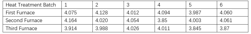
Conclusion: Comparing the above data, permalloy core sheets processed in 3 runs show basically consistent performance, meeting the requirement of being within ±10% of the 4H central value.
Test data for finished transformers before housing assembly: Frequency = 1 kHz (HP4225LCR tester). Measure winding L1–2 (H) at 20°C (room temperature). Specific data is as follows:

After testing, the transformer data remains essentially unchanged after impregnation.
2.3Adjusting Inductance Consistency
A single - sheet interleaving method is adopted. A single EI sheet has a curvature. During insertion, keep the curvature direction consistent. By comparing multiple insertions into the same coil, it is found that when the curvature direction is consistent, the inductance is relatively larger, approximately 18mH. In contrast, if the curvature direction is not consistent during insertion, the inductance is about 15mH. Therefore, using the method of keeping the curvature direction consistent during insertion allows for fine - tuning the inductance by manually adjusting the slight differences in the air gap between E and I sheets, providing adjustment margin or space, and thus achieving better inductance consistency.
Taking the T1 transformer as an example, the center value of T1 is re - determined as 4.00H, controlling the inductance consistency of the transformer within ±10% of the center value. Moreover, it is basically ensured that the inductance of each batch of transformers leaving the factory is essentially consistent with the newly determined center value.