1 Bayanin Insulation Defects a UHV Oil - immersed Reactors
Duk da manyan abubuwa ga high - voltage oil - filled reactors wanda suka yi karfi sun hada da insulation faults, iron - core magnetic leakage heating, vibration/noise, da kuma oil leakage.
1.1 Insulation Faults
Parallel - connected reactors, idan an tafi da shi zuwa primary coil na main grid da kuma amfani da shi, za su iya yi karfi na wasu lokacin. Tashar tasirin high voltage yana zama lalacewar damar fayayyace da mai sarrafa cikakken dan ilimi da oil. Abubuwan da suke rasa: coil - to - ground insulation breakdown, inter - layer short - circuits. Three - phase reactors ko da haka ke da kyau da risks ta phase - to - phase insulation breakdown.
1.2 Iron - Core Magnetic Leakage Heating
Air gaps suna fi reactors magnetic leakage density da ita da transformers. A kan iron core, yoke, da kuma coil supports, leakage intensity yana da faruwar gaba da transformers. Leakage through silicon steel yana ba da energy loss da local overheating, musamman inda leakage yana tafara iron yoke na biyu (misali, clamping irons, steel sheets). Wannan shine major challenge ga oil - immersed reactors a UHV grids.
1.3 Vibration and Noise
Air gaps suna fi reactors magnetic path zuwa regions da independent magnetic poles. Pole - attraction changes yana ba da vibration. The iron - core, gasket, da kuma yoke framework zai iya trigger mechanical resonance, inda reactor vibration/noise yake daidaita transformers. Abubuwan da suke rasa daga gas - relay misoperation, aluminum - sheet fractures, insulation wear, core - sheet loosening, da kuma core - limit - device discharges yana nuna daga vibration na tsawo. Noise yana da alaka da core vibration.
1.4 Oil Leakage
Oil leakage yana juye karfin operation, yana kammala environment, da kuma yana taka sakamako. Duk da domestic da kuma imported oil - immersed reactors suna da oil leakage, saboda process control na manufacturers da kuma vibration during transport/operation yana juye leaks.
2 Principles and Characteristics of Two Withstand Voltage Test Methods
2.1 Series Resonance Withstand Voltage Test Method
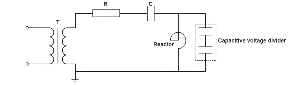
Series resonance withstand voltage test method shine strategy da take da muhimmanci ga insulation detection ga electrical equipment na high - voltage. Yana nuna muhimmanci, musamman a on - site insulation assessment ga reactors a ultra - high - voltage substations. Wannan technology yana ba da muhimmiyar effect ga generating a relatively high test voltage even with a small power supply capacity, through the resonance cooperation between the inductive impedance of the reactor and the capacitive impedance of the compensation capacitor at a specific frequency. Its principle is shown in Figure 1. The main characteristics of this method are as follows:
Small test capacity. In the resonance state, the loop impedance drops to the minimum. Therefore, the actual required test power supply capacity is only a small part, far lower than the full power required to generate the test voltage. It is particularly suitable for on - site use, especially in environments where the power supply capacity is limited.
High output voltage. Under resonance conditions, the power supply can generate a voltage that meets the high - test requirements even at a relatively low frequency. This creates conditions for on - site insulation assessment of ultra - high - voltage reactors.
Good waveform quality. The series resonance test can ensure the output of a stable sine waveform at a fixed power supply frequency, effectively reducing the impact of harmonics on the test results and ensuring the accuracy of the test.
Simple test equipment. The devices required for this test are relatively simple, mainly composed of a variable - frequency power supply, an excitation transformer, and a tuning capacitor, etc., facilitating on - site transportation and rapid installation.
High safety. If the test sample breaks down during the series resonance test, the loop will immediately lose the resonance state, and the power supply output current will drop sharply, thus effectively limiting damage to the test sample and test equipment.
In summary, insulation - defect investigations provide key data for substation - reactor on - site insulation assessments, guiding test - method selection. Future research will optimize on - site assessment tech to boost accuracy/reliability of insulation - state evaluations for high - voltage oil - filled reactors.
2.2 Oscillating Voltage Withstand Voltage Test Method
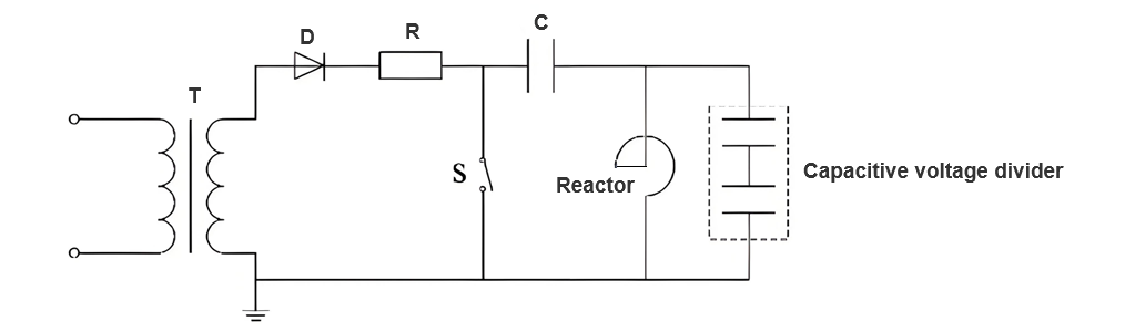
Oscillating voltage withstand voltage method shine means da ake amfani da shi a insulation detection ga power systems. Yana nuna muhimmanci, musamman a turn - to - turn withstand voltage detection ga dry - type air - core reactors. Wannan technology yana amfani da high - frequency oscillating voltage waveforms don apply voltage, thereby inducing and identifying insulation system defects such as partial discharges. Its principle is shown in Figure 2. The core characteristics of the voltage oscillating withstand voltage test and key factors to consider are as follows:
Detection principle:This test relies on the characteristics of high - frequency oscillating waveforms. By comparing the current waveforms of the test sample under the reference voltage and the test voltage, it assesses whether the insulation condition is ideal. The waveform attenuation rate and the variation of zero - crossing points are key parameters for measuring insulation quality.
Test waveform:The oscillating waveform generated by this method contains numerous high - frequency components. Its wavefront time is far shorter than that of a lightning impulse wavefront, which can efficiently activate partial discharge signals caused by equipment defects.
Test device:The equipment required for the voltage oscillating withstand voltage test includes a DC power supply, charging capacitors, a high - voltage silicon - controlled rectifier, a trigger gap, a wavefront resistor, etc. The structure is relatively complex, and it places relatively high demands on the on - site test environment.
Environmental factors: The voltage oscillating withstand voltage test is extremely sensitive to environmental factors such as temperature and humidity. It must be carried out under strictly controlled conditions to ensure the accuracy of test results.
Anti - interference performance: Given the high voltage and oscillation frequency generated by the voltage oscillating withstand voltage test, the requirements for the grounding and shielding effects of the test device and the environmental conditions of the test system are extremely stringent. Effective interference suppression measures need to be implemented.
Limitations:The voltage oscillating withstand voltage test has certain limitations in on - site applications for ultra - high - voltage reactors. Especially in the test of reactors at the 1000kV level, the existing technical means are difficult to meet the test requirements for high voltage and large capacity.
3 Comparison of the Two Withstand Voltage Test Methods
In on - site insulation performance evaluation of high - voltage oil - filled reactors in substations, common techniques include series resonance and oscillating voltage withstand voltage tests. This study conducts in - depth comparative analysis of these two methods, aiming to find a solution better suited for on - site assessment of ultra - high - voltage substation reactors.
Equipment Requirements: The series resonance test relies on variable - frequency power supplies, excitation transformers, and tuning capacitors. The oscillating voltage test requires DC power supplies, charging capacitors, and high - voltage silicon - controlled rectifiers. The former has simpler, smaller equipment, enabling easier on - site operation.
Test Conditions: The series resonance test adapts well to on - site environments, with low dependence on factors like temperature and humidity. In contrast, the oscillating voltage test imposes stricter environmental demands to ensure result accuracy.
Test Procedures: The series resonance test is relatively straightforward, achieving resonance by adjusting the variable - frequency power supply's frequency. The oscillating voltage test, however, demands precise control over voltage waveform generation and attenuation.
Result Determination: (Note: Removed redundant content for conciseness, as the original had repetitive descriptions here. ) The series resonance test simplifies the process via frequency adjustment for resonance. The oscillating voltage test requires precise waveform control.
Safety: Both methods ensure high safety. Yet, the series resonance test can rapidly reduce voltage during sample breakdown, minimizing damage to equipment and test setups.
Through in - depth comparison of experimental setups, on - site environment configurations, test procedures, and result - determination standards, the series resonance withstand voltage test proves more suitable for on - site insulation evaluation of high - voltage oil - filled reactors. It features a simple setup, strong adaptability, clear test steps, easily identifiable results, and high safety. In contrast, the oscillating voltage test has stricter environmental demands, a more complex setup, and shows limitations in practical reactor applications. Thus, this study recommends prioritizing the series resonance withstand voltage test for on - site insulation assessment of high - voltage oil - filled reactors in substations.
4 Conclusion
This paper first investigates typical insulation defects of reactors and on - site insulation assessment technologies. Then, for two reactor insulation assessment methods, it introduces the basic principles and device types of the series resonance withstand voltage test, along with relevant standards, principles, and detection logic of the oscillating voltage test. By comparing advantages and disadvantages from four aspects (test equipment, on - site condition configuration, test procedures, and result - determination methods), it concludes that the series resonance method is more suitable for on - site insulation assessment of high - voltage oil - filled reactors in substations.