• Product
  • Suppliers
  • Manufacturers
  • Solutions
  • Free tools
  • Knowledges
  • Experts
  • Communities
Search


What Are the Types of Reactors Classified by Function and Their Applications?

Echo
Echo
Field: Transformer Analysis
China

Classification of Reactors by Function (Main Applications)

Reactors play a crucial role in power systems. One of the most common and important ways to classify them is by their function — that is, what they’re used for. Let’s take a closer look at each type in simple, easy-to-understand terms.

1. Current-Limiting Reactors

  • Series Reactors
    These reactors are connected in series with the circuit — kind of like a speed bump in the electrical flow.
    Purpose: Increase the impedance of the circuit to limit short-circuit current, reducing both the peak and steady-state values.
    Applications:

    • Limit short-circuit currents at generator outlets, feeders, and busbars;

    • Reduce inrush current during motor startup;

    • Prevent capacitor inrush when switching capacitor banks.

2. Shunt Reactors

  • Neutral Grounded Type (High Voltage Shunt Reactor)
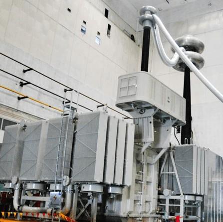
    This type is directly connected to high-voltage transmission lines or the third winding of a transformer.

    • Purpose: Absorb excess capacitive reactive power (also known as charging power) generated by long-distance high-voltage transmission lines. It also helps limit power frequency overvoltage and switching overvoltage.

    • Applications: Used in high-voltage, ultra-high-voltage, and extra-high-voltage transmission systems, such as inter-provincial power lines.

  • Neutral Ungrounded Type
    Usually connected to the busbar in distribution networks at medium or low voltage levels.

    • Purpose: Provide reactive power compensation, offsetting the reactive power from capacitive loads like cable lines. Helps improve power factor and prevent voltage rise ("voltage floating").

    • Applications: Urban power grids, cable-fed systems, and distribution networks.

3. Filter Reactors

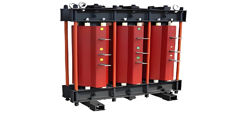
These reactors are typically used in series with capacitors to form an LC filter circuit, acting like a "cleaner" for the power system.

  • Purpose: Filter out specific harmonic currents, usually lower-order harmonics like the 5th, 7th, 11th, and 13th.

  •  Applications:Systems with a lot of harmonic sources, such as large rectifiers, variable frequency drives, and arc furnaces.

It not only protects capacitors from harmonic overcurrent/overvoltage damage but also improves the power quality of the grid.

4. Starting Reactors

This is a special type of current-limiting reactor, specifically used to help motors start smoothly.

Purpose: Connected in series with the stator circuit during startup of large AC motors (e.g., induction or synchronous motors).Limits the starting current and reduces the impact on the power grid. Once the motor starts, it’s usually shorted out or switched off.

Applications: Used for high-power motors like large pumps and fans in factories.

5. Arc Suppression Coils (Petersen Coils)

This is a special iron-core reactor, usually connected to the neutral point of the system — like a "fire extinguisher" for grounding systems.
Purpose: In ungrounded or resonant-grounded systems (i.e., systems with neutral grounded through an arc suppression coil), when a single-phase ground fault occurs, it generates an inductive current to cancel out the system’s capacitive ground current. This significantly reduces or even automatically extinguishes the fault current at the fault point, preventing intermittent arc grounding and overvoltage.
Applications: Distribution networks, small-capacity transformer systems.

Types of arc suppression coils:

  • Adjustable Type (manual or automatic adjustment of inductance)

  • Fixed Compensation Type (fixed inductance)

  • Bias or DC Magnetization Type (adjust inductance by changing the DC magnetizing current)

6. Smoothing Reactors (DC Reactors)

These reactors are used specifically in HVDC (High Voltage Direct Current) transmission systems, connected in series on the DC side of the converter station or DC line.
Purpose:

  • Suppress ripple in DC current (smooth out fluctuations);

  • Prevent commutation failure on the rectifier side;

  • Limit the rate of current rise (di/dt) during DC line faults;

  • Maintain continuity of DC current and prevent current interruption.

Applications: HVDC transmission systems, flexible DC transmission projects.

7. Damping Reactors

Usually connected in series with capacitor circuits, especially in filter capacitor banks.

Purpose:

  • Limit inrush current and overvoltage when capacitor banks are switched on;

  • Suppress oscillations at certain frequencies, such as resonance with system inductance.

Applications: Frequent capacitor switching scenarios, such as in reactive power compensation devices and filter banks.

In Summary

There are many types of reactors, each with its own function, but their main purposes are to:Stabilize current, regulate voltage, filter harmonics, limit surges, and protect equipment.
Choosing the right reactor not only improves the stability of the power system but also extends the life of equipment and ensures safe power supply.

Give a tip and encourage the author!
Recommended
3D Wound-Core Transformer: Future of Power Distribution
Technical Requirements and Development Trends for Distribution Transformers Low losses, especially low no-load losses; highlighting energy-saving performance. Low noise, particularly during no-load operation, to meet environmental protection standards. Fully sealed designto prevent transformer oil from contacting external air, enabling maintenance-free operation. Integrated protection devices within the tank, achieving miniaturization; reducing transformer size for easier on-site installation. C
Echo
10/20/2025
Reduce Downtime with Digital MV Circuit Breakers
Reduce Downtime with Digitized Medium-Voltage Switchgear and Circuit Breakers"Downtime" — it’s a word no facility manager wants to hear, especially when it’s unplanned. Now, thanks to next-generation medium-voltage (MV) circuit breakers and switchgear, you can leverage digital solutions to maximize uptime and system reliability.Modern MV switchgear and circuit breakers are equipped with embedded digital sensors that enable product-level equipment monitoring, providing real-time insights into the
Echo
10/18/2025
One Article to Understand the Contact Separation Stages of a Vacuum Circuit Breaker
Vacuum Circuit Breaker Contact Separation Stages: Arc Initiation, Arc Extinction, and OscillationStage 1: Initial Opening (Arc Initiation Phase, 0–3 mm)Modern theory confirms that the initial contact separation phase (0–3 mm) is critical to the interrupting performance of vacuum circuit breakers. At the beginning of contact separation, the arc current always transitions from a constricted mode to a diffused mode—the faster this transition, the better the interruption performance.Three measures c
Echo
10/16/2025
Advantages & Applications of Low-Voltage Vacuum Circuit Breakers
Low-Voltage Vacuum Circuit Breakers: Advantages, Application, and Technical ChallengesDue to their lower voltage rating, low-voltage vacuum circuit breakers have a smaller contact gap compared to medium-voltage types. Under such small gaps, transverse magnetic field (TMF) technology is superior to axial magnetic field (AMF) for interrupting high short-circuit currents. When interrupting large currents, the vacuum arc tends to concentrate into a constricted arc mode, where localized erosion zones
Echo
10/16/2025
Send inquiry
Download
Get the IEE Business Application
Use the IEE-Business app to find equipment, obtain solutions, connect with experts, and participate in industry collaboration anytime, anywhere—fully supporting the development of your power projects and business.