• Product
  • Suppliers
  • Manufacturers
  • Solutions
  • Free tools
  • Knowledges
  • Experts
  • Communities
Search


Arc Suppression Coil or Petersen Coil

Encyclopedia
Encyclopedia
Field: Encyclopedia
0
China

Arc Suppression Coil Definition


An arc suppression coil, also known as a Petersen coil, is an inductive coil used to neutralize the capacitive charging current in underground power networks during an earth fault.


Purpose and Function


The coil reduces the large capacitive charging current during an earth fault by creating an opposite inductive current.


Working Principle


The inductive current generated by the coil cancels out the capacitive current, preventing arcing at the fault point.


Capacitive Current in Underground Systems


Underground cables have a continuous capacitive current due to the dielectric insulation between the conductor and the earth.


Inductance Calculation


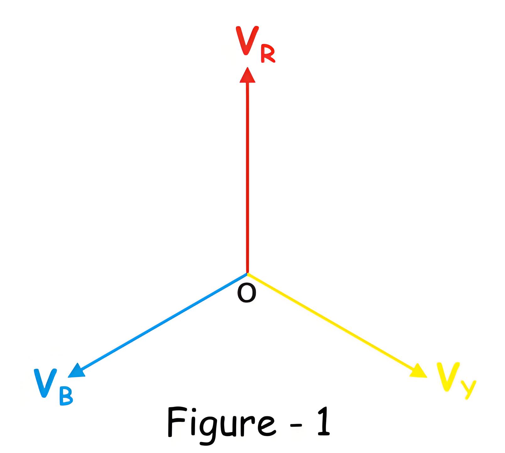
The voltages of a three phase balanced system is shown in figure – 1.


In underground high voltage and medium voltage cable networks, each phase has capacitance between the conductor and the earth, leading to a continuous capacitive current. This current leads the phase voltage by 90 degrees as shown in figure – 2.


2c625f51e0b220920728e226a9a14a3d.jpeg

a6ccb9896da0ce6e866a9141547d580d.jpeg


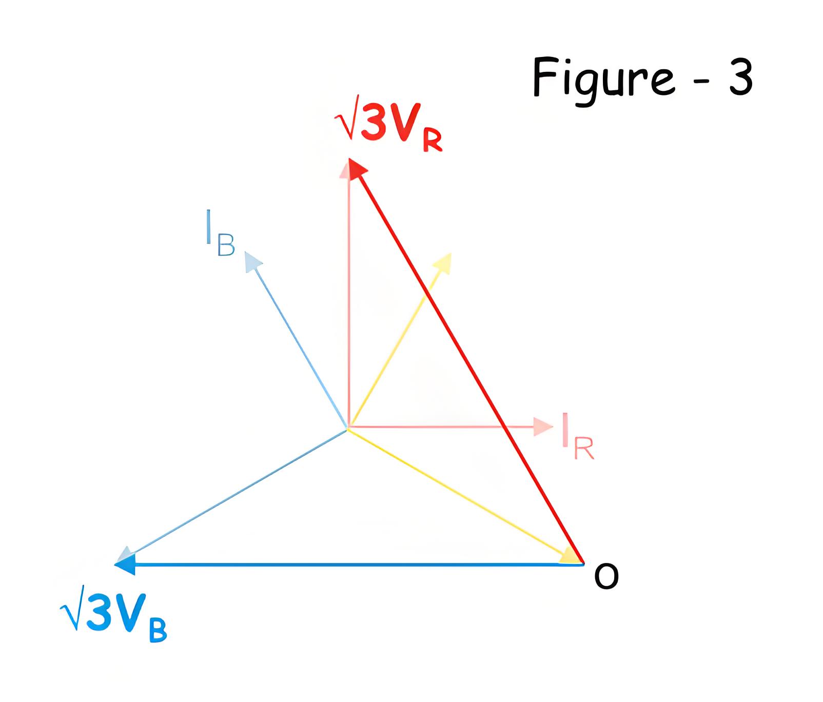
If an earth fault occurs in the yellow phase, the voltage of the yellow phase to ground becomes zero. The system’s neutral point shifts to the tip of the yellow phase vector. Consequently, the voltage in the healthy phases (red and blue) increases to &sqrt;3 times the original value.


a6ccb9896da0ce6e866a9141547d580d.jpeg


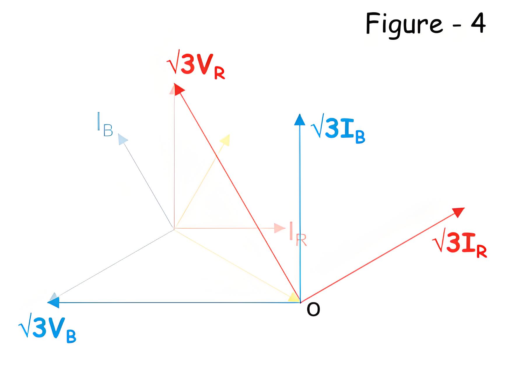
Naturally, the corresponding capacitive current in each healthy phase (red and blue) becomes &sqrt;3 of the original as shown in figure-4, below.


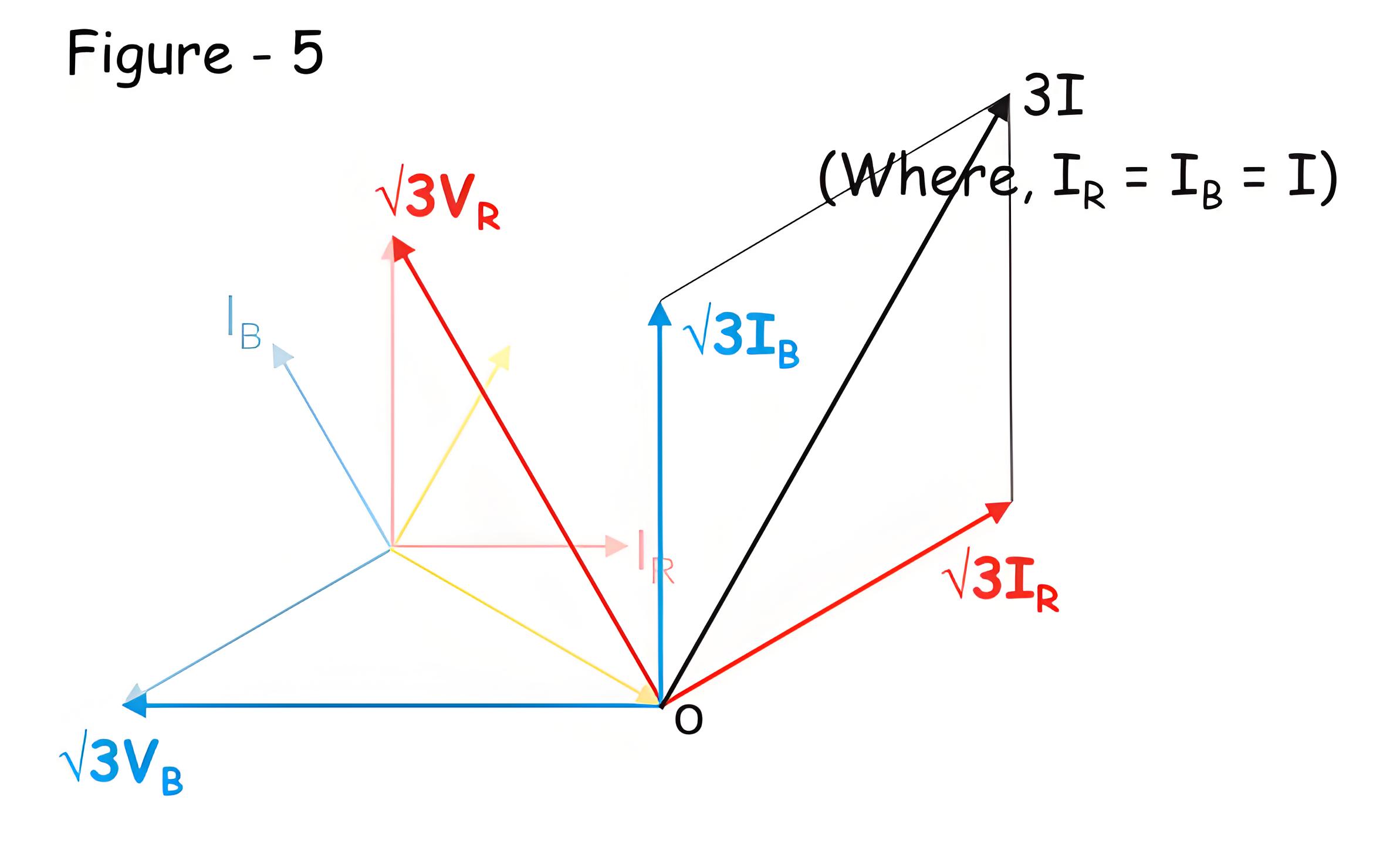
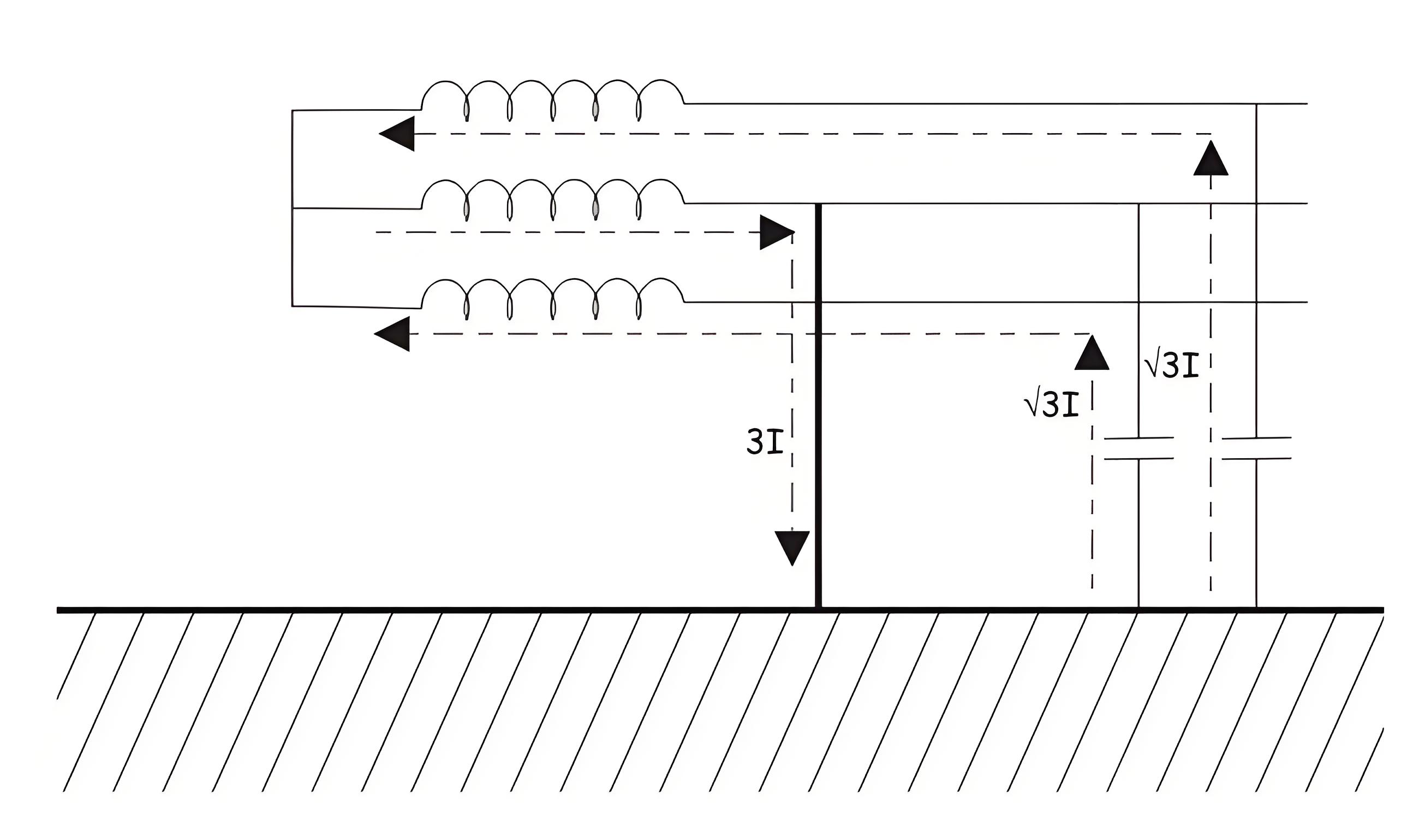
The vector sum that is resultant of these two capacitive current now will be 3I, where I is taken as rated capacitive current per phase in the balanced system. That means, at healthy balanced condition of the system, I R = IY =IB = I.


496665dfb04f5a88f973e1b0b79fd896.jpeg


This is illustrated in the figure- 5 below,


This resultant current then flows through the faulty path to the earth as shown below.


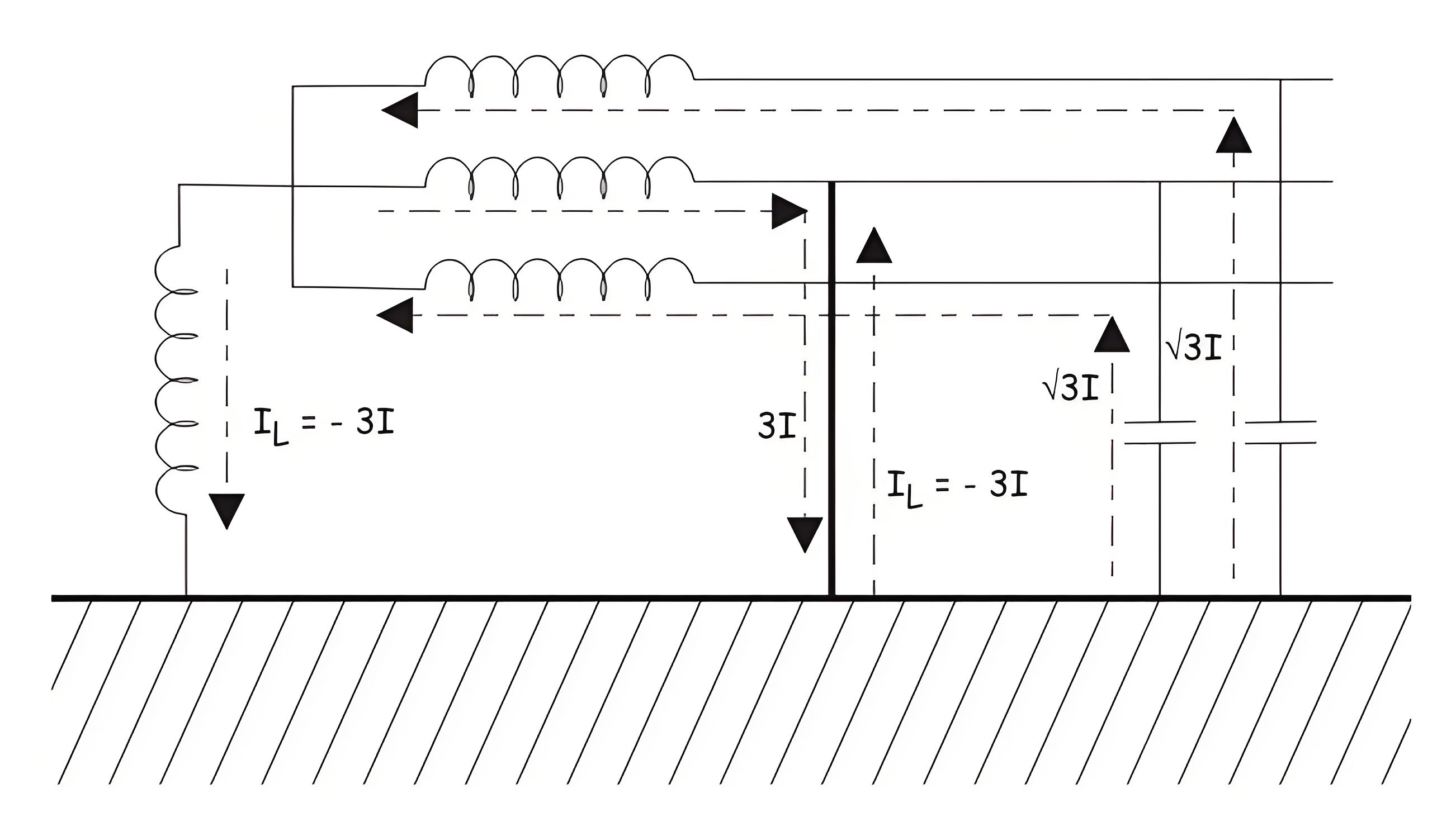
Now, if we connect one inductive coil of suitable inductance value (generally iron core inductor is used) between star point or neutral point of the system and ground, the scenario will be entirely changed. At faulty condition, the current through the inductor just equal and opposite in magnitude and phase of that of capacitive current through the faulty path. The inductive current also follow the faulty path of the system. The capacitive and inductive current cancels each other at the faulty path, hence there will not be any resultant current through the faulty path created due to capacitive action of the underground cable. The ideal situation is illustrated in the figure below.


This concept was first implemented by W. Petersen in 1917, that why the inductor coil is used for the purpose, called Petersen Coil.


dc14df4d10a6332e2daba580133d8d4d.jpeg

663b55f33b2a661d7044d160bf991cfc.jpeg

0660e51009e91fefb60efc9d1dbf1352.jpeg


The capacitive component of the fault current is high in the underground cabling system. When earth fault occurs, the magnitude of this capacitive current through the faulty path becomes 3 times more than rated phase to earth capacitive current of healthy phase. This causes significant shifting of zero crossing of current away from zero crossing of voltage in the system. Due to presence of this high capacitive current in the earth fault path there will be a series of re-striking at fault location. This may lead unwanted over voltage in the system.


The inductance of the Petersen Coil is selected or adjusted at such value which causes the inductive current which can exactly neutralize the capacitive current.

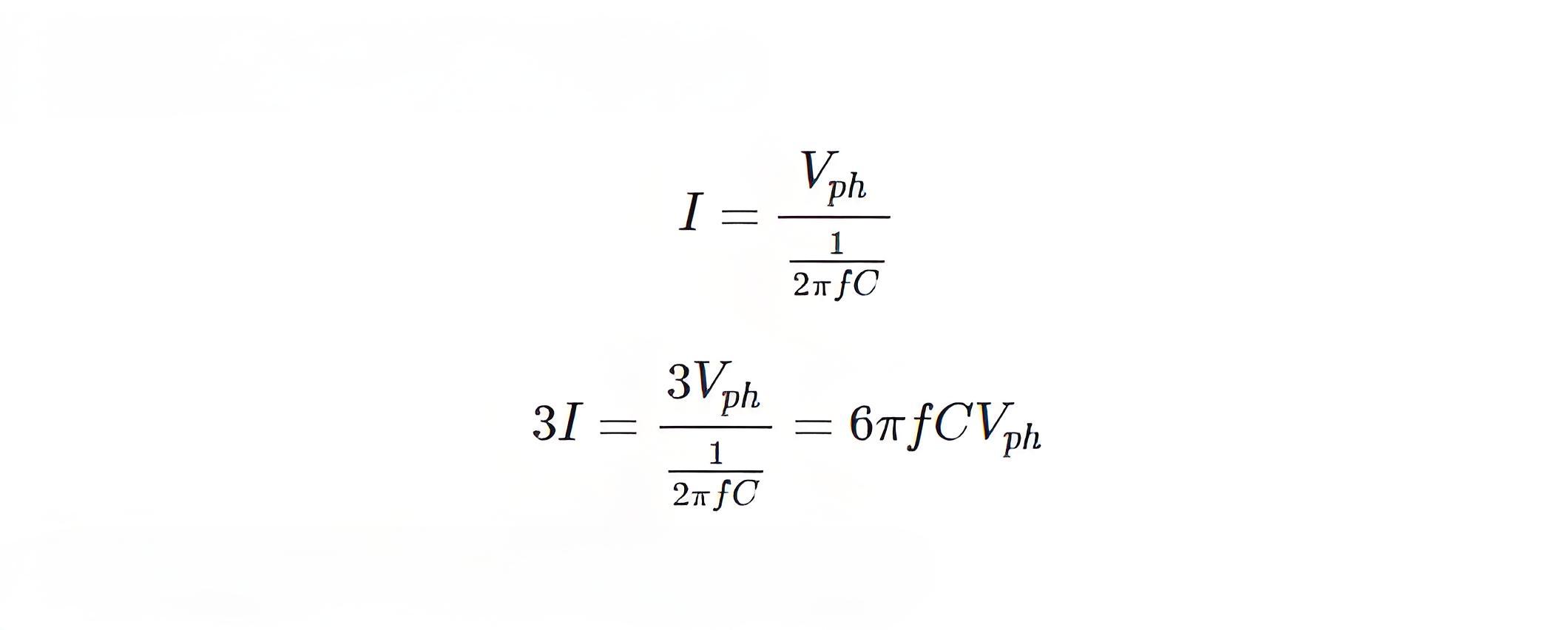
Let us calculate the inductance of Petersen Coil for a 3 phase underground system.For that let us consider capacitance between conductor and earth in each phase of a system, is C farad. Then the capacitive leakage current or charging current in each phase will be


So, the capacitive current through the faulty path during single phase to earth fault is


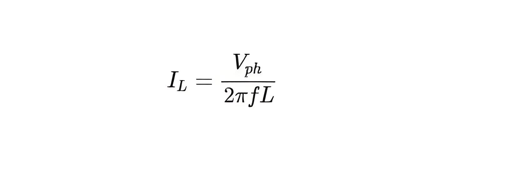
After fault, the star point will have phase voltage as the null point is shifted to fault point. So the voltage appears across the inductor is Vph. Hence, the inductive current through the coil is


4a0132db7deae91e16e7a181f2daa916.jpeg


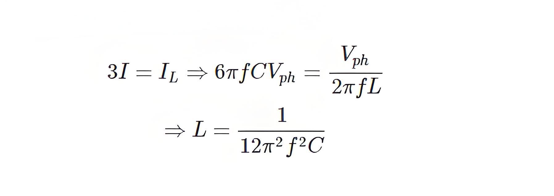
Now, for cancellation capacitive current of value 3I, IL must have same magnitude but 180o electrically apart. Therefore,


8a96d717cfdbcbbaf699ee75a76b8e97.jpeg


When the design or configuration of the system changes, such as length, cross-section, thickness, or insulation quality, the inductance of the coil must be adjusted. Therefore, Petersen coils often have a tap-changing arrangement.


b389513abf0c0cfc782caeb2e52b4b13.jpeg


Give a tip and encourage the author!
Recommended
MVDC: Future of Efficient, Sustainable Power Grids
The Global Energy Landscape Is Undergoing a Fundamental Transformation toward a "fully electrified society," characterized by widespread carbon-neutral energy and the electrification of industry, transportation, and residential loads.In today’s context of high copper prices, critical mineral conflicts, and congested AC power grids, Medium-Voltage Direct Current (MVDC) systems can overcome many limitations of traditional AC networks. MVDC significantly enhances transmission capacity and efficienc
Edwiin
10/21/2025
Grounding Causes of Cable Lines and the Principles of Incident Handling
Our 220 kV substation is located far from the urban center in a remote area, surrounded primarily by industrial zones such as Lanshan, Hebin, and Tasha Industrial Parks. Major high-load consumers in these zones—including silicon carbide, ferroalloy, and calcium carbide plants—account for approximately 83.87% of our bureau’s total load. The substation operates at voltage levels of 220 kV, 110 kV, and 35 kV.The 35 kV low-voltage side mainly supplies feeders to ferroalloy and silicon carbide plants
Felix Spark
10/21/2025
Overhead Power Lines & Towers: Types, Design & Safety
Besides ultra-high voltage AC substations, what we encounter more frequently are power transmission and distribution lines. Tall towers carry conductors that leap across mountains and seas, stretching into the distance before reaching cities and villages. This is also an interesting topic—today, let's explore transmission lines and their supporting towers.Power Transmission and DistributionFirst, let’s understand how electricity is delivered. The electric power industry primarily consists of fou
Encyclopedia
10/21/2025
Automatic Reclosing Modes: Single, Three-Phase & Composite
General Overview of Automatic Reclosing ModesTypically, automatic reclosing devices are categorized into four modes: single-phase reclosing, three-phase reclosing, composite reclosing, and disabled reclosing. The appropriate mode can be selected based on load requirements and system conditions.1. Single-Phase ReclosingMost 110kV and higher transmission lines employ three-phase single-shot reclosing. According to operational experience, over 70% of short-circuit faults in high-voltage overhead li
Edwiin
10/21/2025
Send inquiry
Download
Get the IEE Business Application
Use the IEE-Business app to find equipment, obtain solutions, connect with experts, and participate in industry collaboration anytime, anywhere—fully supporting the development of your power projects and business.