Housed in Vaults
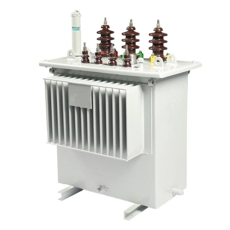
Network transformers, which are distribution transformers serving grid and spot networks, are large - sized three - phase units.

According to ANSI C57.12.40 - 1982, network units are typically categorized as vault - type or subway - type:
Network transformers are also employed in buildings, typically in the basement. In such cases, vault - type transformers can be utilized, provided that the room is properly constructed and safeguarded for this purpose.Utilities may also opt for dry - type units and units with less - flammable insulating oils.
Technical Characteristics
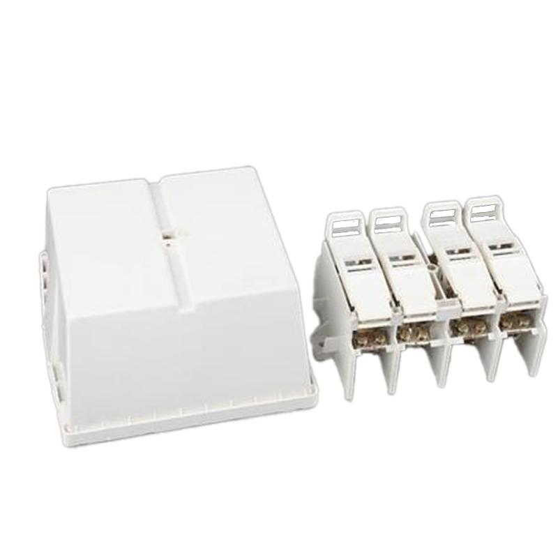
A network transformer is equipped with a three - phase primary - side switch, which is capable of opening, closing, or short - circuiting the primary - side connection to ground. Its standard secondary - side voltages are 216Y/125 V and 480Y/277 V. Table 1 below lists the standard specifications.

Transformers with a rated capacity of 1000 kVA or less have an impedance of 5%; for those with a rated capacity exceeding 1000 kVA, the standard impedance is 7%.
The reactance - to - resistance ratio (X/R) generally ranges from 3 to 12. Transformers with lower impedance (such as those with a 4% impedance) exhibit lower voltage drops and higher secondary - side fault currents. (Higher secondary - side fault currents are beneficial for clearing faults in the network.) However, lower impedance comes at a cost – it results in higher circulating currents and poorer load balancing among transformers.

Transformers with a rated capacity of 1000 kVA or less have an impedance of 5%; for those with a rated capacity exceeding 1000 kVA, the standard impedance is 7%.The reactance - to - resistance ratio (X/R) generally ranges from 3 to 12. Transformers with lower impedance (such as those with a 4% impedance) exhibit lower voltage drops and higher secondary - side fault currents. (Higher secondary - side fault currents are beneficial for clearing faults in the network.) However, lower impedance comes at a cost – it results in higher circulating currents and poorer load balancing among transformers.
Grounding connections
Most network transformers are connected delta – grounded wye.By blocking the zero - sequence current, this connection keeps the grounding current on the primary cables at a low level. Consequently, a highly - sensitive ground - fault relay can be employed on the substation circuit breaker. Blocking the zero - sequence current also reduces the current on the cable neutrals and cable sheaths, including zero - sequence harmonics, predominantly the third harmonic.In the event of a primary line - to - ground fault, the feeder circuit breaker trips, yet the network transformers will continue to backfeed the fault until all network protectors operate (and some may malfunction). At this point, the network transformers backfeed the primary feeder as an ungrounded circuit.
In an ungrounded circuit, a single - phase line - to - ground fault causes a neutral - point shift, which raises the phase - to - neutral voltage of the unfaulted phases to the phase - to - phase voltage level. Non - network loads connected phase - to - neutral will be exposed to this overvoltage.Some networks adopt the grounded wye - grounded wye connection method.

This connection is more suitable for combination feeders. In the event of a primary line - to - ground fault, the feeder circuit breaker trips. For the backfeed current to the primary through the network, the wye - wye connection still provides a grounding reference point, thus reducing the likelihood of overvoltage.The grounded wye - grounded wye connection also decreases the probability of ferroresonance when the transformer undergoes single - pole switching.
Most network transformers are of the core type, with the core structure being either three - legged (three - phase, three - column) or five - legged (three - phase, five - column). The three - legged core, whether it is a stacked core or a wound core, is suitable for a delta - grounded wye connection (but not for a grounded wye - grounded wye connection due to tank heating issues). A five - legged core transformer is suitable for both of the above - mentioned connection types.