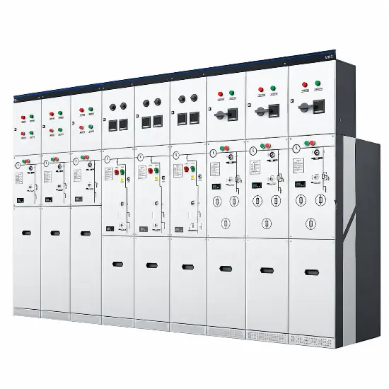
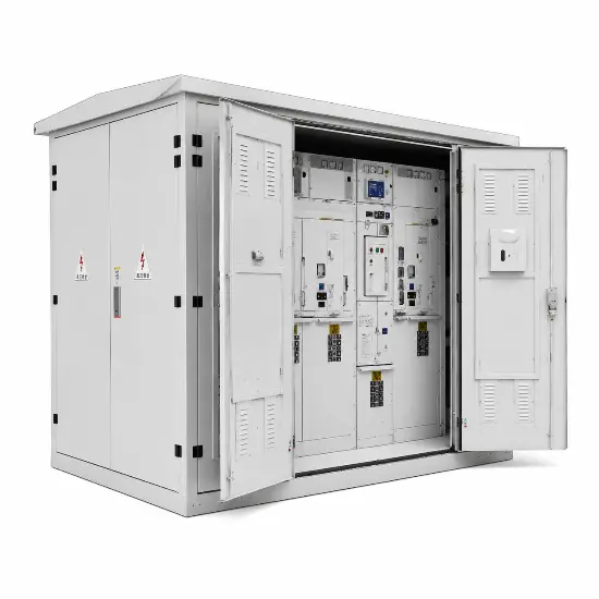
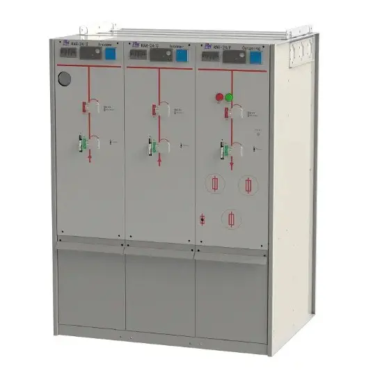
As a senior expert in power systems and high-voltage engineering, I will provide a technical analysis of Ring Main Unit (RMU) distribution, focusing on the logic and configuration of incoming and outgoing feeders.
In modern urban distribution networks, the RMU serves as the "nerve center." It is not just a piece of switchgear; it is the physical realization of the ring network topology, ensuring high power reliability (N-1 criteria) for critical infrastructure and residential areas.
1. The Strategic Role of RMUs in Power Distribution
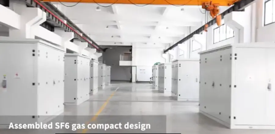
A Ring Main Unit is a factory-assembled, metal-enclosed set of switchgear used at the load connection points of a ring-type distribution network. Its primary function is to facilitate the "Ring Main" logic:
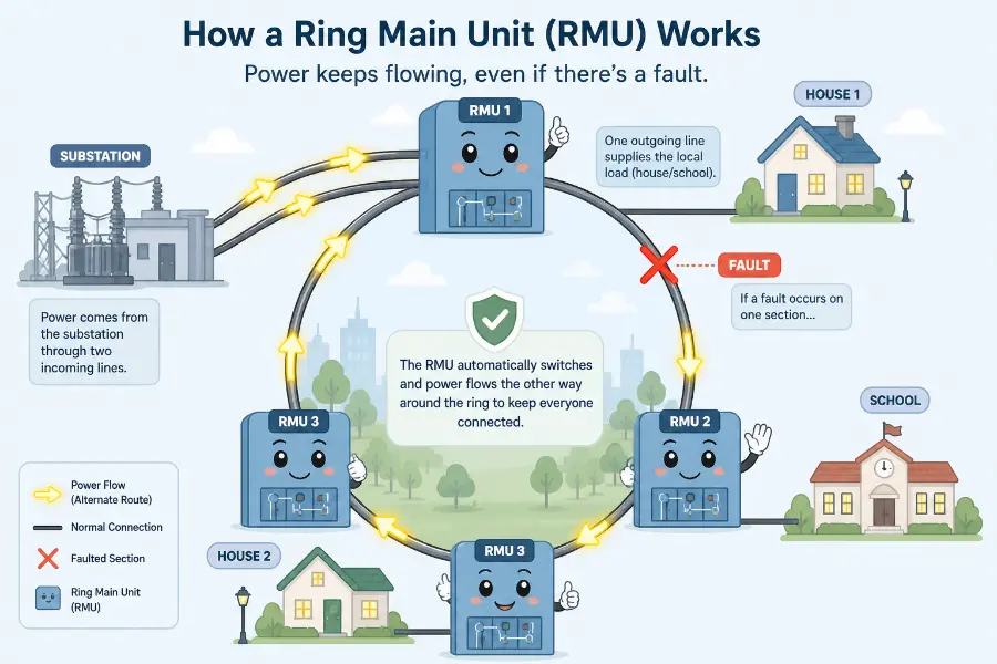
- Normal Operation: The ring is typically operated in an open-loop configuration at a designated "normally open point" to limit fault currents and simplify protection coordination.
- Fault Scenario: If a cable segment fails, the RMUs allow for rapid fault isolation. By switching the "normally open point," power can be restored from an alternative path, minimizing downtime.
2. Incoming Units: The "Relay" of the Ring
Incoming units are responsible for connecting the RMU to the primary ring cables. A standard RMU configuration (e.g., a "2+1" setup) includes two incoming feeders to facilitate the "in-and-out" looping of the main cable.
- Switching Device: Most incoming units utilize a Load Break Switch (LBS), typically insulated with SF6 gas or solid dielectric materials. The LBS is designed to interrupt rated load currents and close onto short-circuit currents, but it does not interrupt fault currents (which are handled by the upstream substation circuit breaker).
- Safety Logic: These units feature a three-position switch (Closed, Open, Earthed). The earthing switch is mechanically interlocked to ensure that the cable side can only be grounded when the main switch is open, providing a safe environment for maintenance.
- Monitoring: Integrated voltage indicators are mandatory to prevent accidental grounding of energized cables.
3. Outgoing Units: The "Shield" for Transformers
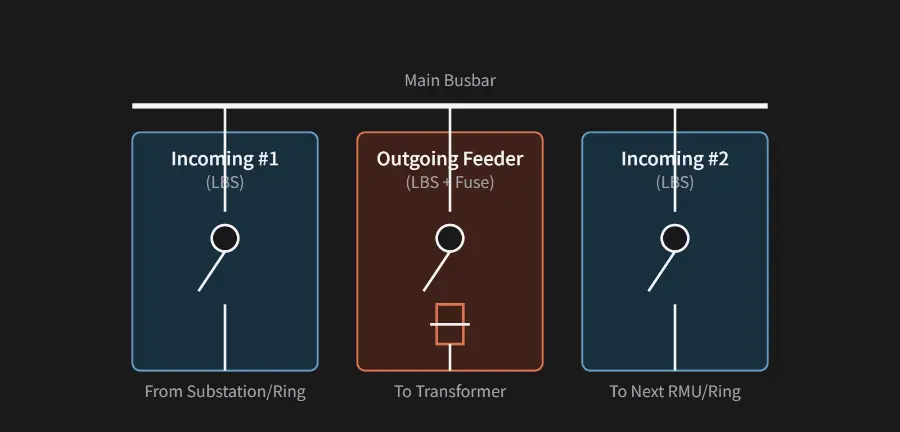
The outgoing unit (or tee-off) distributes power from the main busbar to the local distribution transformer or branch loads. This is where the protection logic resides.
- Scheme A: Fuse-Switch Combination (F-L Unit)
- Application: For transformers up to 1250kVA.
- Logic: Uses an LBS for operational switching and High-Voltage Current-Limiting Fuses for short-circuit protection. A striker mechanism in the fuse triggers the LBS to trip all three phases simultaneously if any fuse blows.
- Scheme B: Vacuum Circuit Breaker (VCB Unit)
- Application: For large transformers (>1250kVA) or industrial customers requiring sophisticated protection.
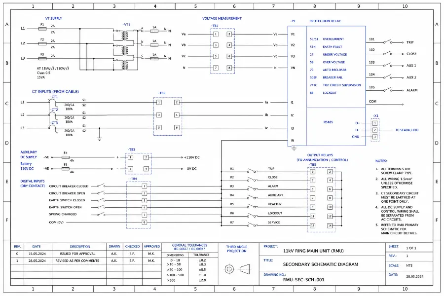
- Logic: Equipped with a VCB and a micro-processor-based protection relay. It offers multiple protection stages (Overcurrent, Short-circuit, Earth-fault) and supports automation protocols like IEC 60870-5-104 or DNP3.
The diagram below illustrates the electrical topology of a typical RMU configuration:
4. Engineering Practices for Cable Terminations
In the field, the physical connection of incoming and outgoing cables requires meticulous attention to engineering standards:
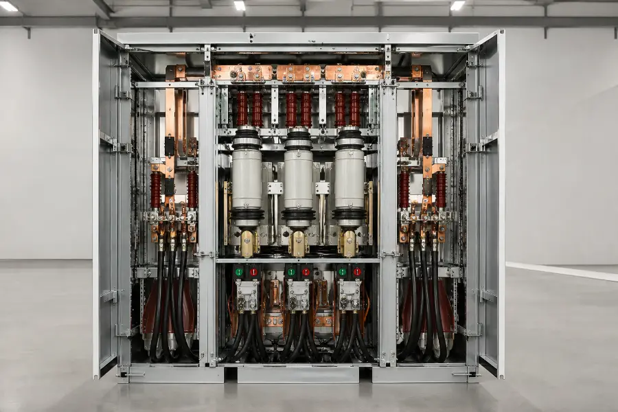
- Screened Connectors: Modern RMUs utilize touch-proof separable connectors (e.g., T-type or elbow connectors). These have a semi-conductive outer layer that is grounded, ensuring personnel safety during operations behind the panel.
- Environmental Sealing: Since RMUs are often located in basements or outdoor kiosks, cable entries must be moisture-sealed. SF6-insulated or solid-insulated (APG process) units are preferred to eliminate flashover risks caused by condensation.
- Zero-Sequence CT Installation: To accurately detect earth faults, the cable's grounding wire must be passed back through the zero-sequence Current Transformer (CT) before being connected to the earth bar. Failure to do so will result in the CT failing to detect the fault current.
5. Conclusion
The design of RMU incoming and outgoing units is a balance between connectivity and protection. While incoming units ensure efficient ring maintenance, outgoing units act as high-speed guardians for local assets. As we move toward Smart Grids, these units are becoming increasingly "digital," integrating sensors for temperature, partial discharge (PD), and automated fault location, isolation, and service restoration (FLISR).
Contact us:
Edited From:Dyson

 Login
Login