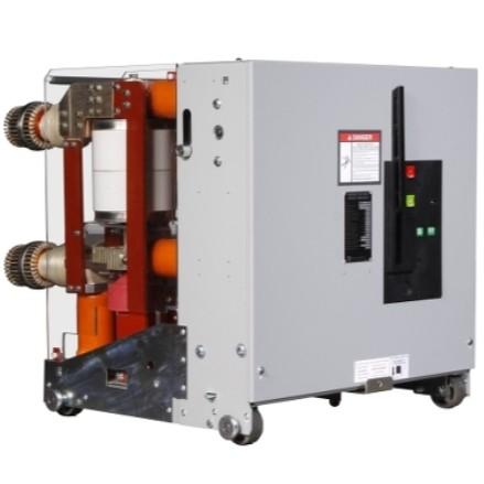
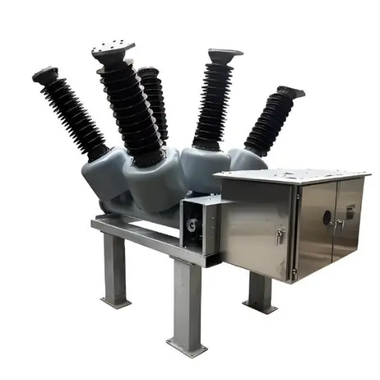
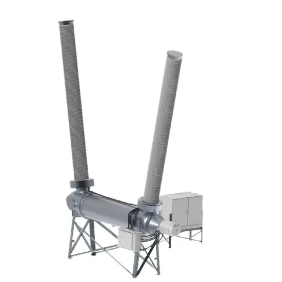
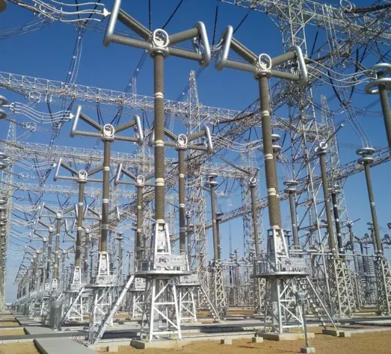
At present, most low - voltage switchgear assemblies in China mainly use SF₆ gas at a pressure of 0.5 - 0.6 MPa as the insulating medium. However, when the ambient temperature drops to around - 32.5°C, the SF₆ gas will quickly liquefy, resulting in serious problems with the insulation and interrupting capabilities of the product. To avoid affecting the operation of low - voltage switchgear assemblies in alpine regions, tracing heaters are often used to prevent the liquefaction of SF₆ gas. Nevertheless, during the actual operation of tracing heaters, it is impossible to thoroughly inspect their specific working status from the outside, which also has a certain impact on the operation and maintenance of the product.
Main Working Principle and Current Situation of the Tracing Heater for 500kV Substation Tank - type Circuit Breakers
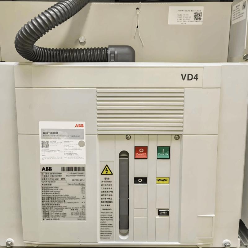
Since SF₆ circuit breakers are prone to being affected by liquefaction problems in alpine regions, adding a tracing heater to the circuit breaker casing can ensure the prevention of liquefaction. Once the working environment temperature drops rapidly, the temperature controller of the tracing heater will automatically start operating to keep the gas inside the circuit breaker continuously heated. When the temperature drops to - 15°C, the temperature controller will automatically activate, and after the contacts close, it will ensure continuous heating of the tracing heater. If the tracing heater is damaged or the temperature controller fails to start properly, it is difficult to observe from the outside, which affects the operation of the entire circuit breaker.
Technical Scheme Design for Monitoring the Tracing Heater of 500kV Substation Tank - type Circuit Breakers
To further improve the overall operation effect of the tracing heater monitoring system, the key is to effectively control the current isolator connected in series to the working circuit of the tracing heater through a monitoring technical scheme. After isolating the starting control device and the current isolator for current collection, the status indicator light driven by the current can be effectively monitored. By observing the indicator light, important references can be provided for the staff. In the process of designing the tracing heater monitoring technology, the main measure is to add an automatic switch to directly control the tracing heater, enabling manual adjustment even during the daily operation of the temperature controller.

In the design of the monitoring technical scheme for a single - piece tracing heater, its main power is 2400W, and the working current is 10.09A. By monitoring the tracing heater, the working current in the circuit can be monitored in real - time. A current isolator with a current ratio of 15/5A can quickly convert the large current of 10.09A into a small current within 3.6A, avoiding the problem of excessive heating of the circuit coil. Moreover, the current range can be quickly adjusted to 2 - 9.9A, enabling accurate judgment of the secondary output current of the collected current isolator, and ensuring that the output action node drive is consistent with the working status of the circuit status indicator light.
Monitoring System for the Tracing Heater of 500kV Substation Tank - type Circuit Breakers
Device Usage Method
Start the program by clicking the shortcut of "Linhai Tracing Heater Monitoring" on the Win10 system desktop to open the virtual machine and enter the WinXP system. Then click the shortcut of "Tank - type Circuit Breaker Tracing Heater Monitoring" to start the program and enter the tracing heater operation monitoring screen. Through the parameter setting interface, you can set the alarm threshold for the tracing heater current and the alarm threshold for the tracing heater not operating when the ambient temperature is lower than a certain value.
It also provides the display of the temperature in the centralized control box and the setting of the starting temperature for the heater and fan in the box. Click the operation record, select the device number to be queried through the device selection drop - down box, and query the operation record of the device for a certain period. Open the fault record to query the fault record of the device for a certain period.The tracing heater monitoring system can realize computer - controlled testing of equipment, greatly shortening the testing time and improving the testing accuracy.
Configuration information can be configured in the background and stored in the database, and professional configuration information can be read from the database. For common tracing heaters, only classified configuration is required. When the test items and parameters change, only the corresponding information needs to be modified, greatly reducing errors caused by repetitive operations. By identifying the current signal sent by the transmitting end at the receiving end, the transceiver line sequence can be automatically matched successively, eliminating the trouble of determining the line sequence through multiple communications between the manual sending and receiving ends.
In addition, the tracing heater monitoring system needs to save the test results and judge the corresponding results, and prompt for optical fibers that do not meet the index requirements. Besides the above - mentioned functions, the tracing heater monitoring system should be equipped with a touch screen for the convenience of operators. To ensure that the tracing heater monitoring system developed for the project meets relevant standards and specifications, specific technical index requirements are put forward for the tester from five aspects: overall function, overall performance, laser source performance, laser detector performance, and general requirements.

The general requirements are further divided into four aspects: working environment, appearance, safety, and electromagnetic compatibility (EMC). The indicators that must be met are listed as key indicators. Broadly speaking, in addition to the testing instrument, the tracing heater monitoring system should also include testers, test objects, and the environment. A tracing heater monitoring system that requires full - time human participation to complete specific testing tasks for the unit under test is called a manual tracing heater monitoring system. On the contrary, a tracing heater monitoring system that requires only a small amount of human participation and can automatically complete most testing tasks is called an automatic testing system.
Main Advantages of the Monitoring Technology Design for the Tracing Heater of 500kV Substation Tank - type Circuit Breakers
The design of the tracing heater monitoring technology enables operating personnel to intuitively judge the specific operation status of the tracing heater, avoiding threats to the operators. At the same time, the entire tracing heater monitoring technology has a very strong anti - interference ability. Through the output of moving and moving - break contacts, it can be directly monitored in the main control room, facilitating the use of users. The entire monitoring system is very simple. It only requires passing the heater wire through the current isolator and connecting the indicator light externally.
Conclusion
In conclusion, the tracing heater monitoring system can help operating personnel visually judge the specific operation status of the tracing heater from the outside, providing an accurate operation reference for management and maintenance. The tracing heater monitoring system can also effectively reduce the problem of the tracing heater not working properly, ensuring that faults are detected and solved in a timely manner and guaranteeing the safe and reliable operation of the substation.


