An fitowa da circuit breakers na DC na masu matsayin tsakiyar jirgin lafiya suka da amfani a cikin daji, metro urban, tsafta mai zurfi, microgrids (yanayi mai zurfi), distributed generation (energy ta shamsi), da kuma systems na battery (data centers).
A nan bayan da impedance na circuit ya fi yawa a kasar DC, zai iya rarrabe short circuits da ma'ana masu yawa. Kuma saboda an ba suka ci gaba da transformer windings zuwa time constant a cikin systems na DC, time constant na yau da kullum ya kuce da ya fi yawa, kuma short circuit zai iya haɗa da rise times da suka duba milliseconds guda. Zan iya hada da voltage collapse idan ake yi amfani da kadan 80% na nominal DC voltage don voltage source converter (VSC) station ta yi aiki daidai.
Don in kammala disruptions na converter, fault ya kamata a ce a kan milliseconds guda, musamman don stations da ba suka ci gaba da line ko cable da take faru.
Nau'ukan da turanci na circuit breakers na DC na masu matsayin tsakiyar jirgin lafiya a sashe:
Tsohon nau'ukan da ke cikin sashe na LVDC da MVDC sun hada da solid-state circuit breakers (SSCBs), mechanical circuit breakers (MCBs), da kuma hybrid circuit breakers (HCBs) wanda yake da SSCB a parallel da ultra-fast mechanical switch (UFMS).
Conventional air and SF6-based LV and MV AC MCBs suna da capability na DC interrupting wanda yake da limits kafin kilovolts da kuma Ampers guda.
Solid-state medium voltage DC circuit breakers:
Topologies for SSCBs suna da Integrated Gate Commutated Thyristors (IGCTs), Gate Turn-Off Thyristors (GTOs), ko kuma Insulated Gate Bipolar Transistors (IGBTs), connected in series. Saboda response times suna da yawan takwas, amma wani abin da ke nuna shine on-state losses da ke cikin range na 15-30% na losses na VSC station.
High component costs, lack of galvanic isolation, da kuma inadequate thermal absorption capacity suna da muhimmanci a cikin disadvantages.
Figure 1 yana nuna wani type da solid-state medium voltage DC circuit breaker design:

Figure 1: a) IGCT-based medium voltage bi-directional solid-state circuit breaker, (b) IGCT-based medium voltage bi-directional solid-state circuit breaker, (c) GTO-based bidirectional solid-state circuit breaker
Different SSCB topologies suna da proposal. Amma, akwai mafi yawan adadin da suka da voltages ≤ 1 kV, musamman da low currents ≤ 1000 A. Yana da kyau a sanin cewa one of the most challenging aspects of SSCB technology shine high on-state loss, kuma although some articles report an MV SSCB satisfying an MV voltage level such as of 6-15 kV, they are typically for rated current less than 1000 A, But required power handling capacity would be in some MWs to a few tens of MWs range with at least 3 parallel modules (3P:3*3.72 MW).
Thus, developing a DC CB with a rated power of less than 10 MW for future MVDC architectures becomes almost useless. The current power semiconductor technologies cannot meet such power ratings; consequently, SSCBs for the future MVDC architectures will not lead to a highly efficient cost-effective compact design. In this regard, relatively large air blowers with capacities around six thousand cubic feet per minute and/or active water cooling are needed for the multi-kilowatt levels of on-state loss anticipated for high currents.
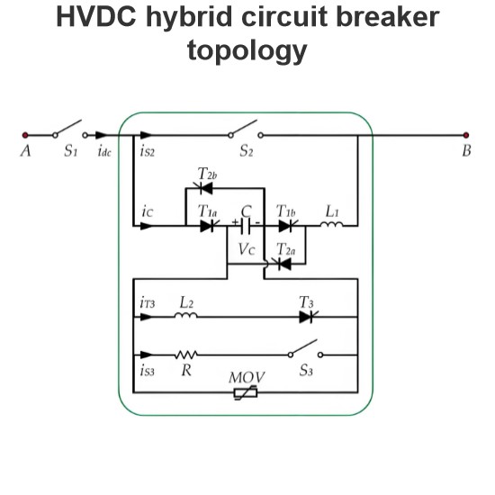
Hybrid medium voltage DC circuit breakers (HCBs):
Hybrid medium voltage DC circuit breakers include a current conduction path and a current interruption path.
A hybrid breaker combines the exceptionally low forward losses of a pure ultrafast switch with the quick performance of a solid-state breaker in the parallel path. The main breaker is positioned on a parallel path and is made up of a series and parallel solid-state switches that are connected in series.
A developed a modular HCBand one module as shown in Fig. 2 with rated voltage and current, and a current breaking capability of 6.2 kV, and 600 A, respectively.
It’s worth noting that the ultrafast switch’s arc chamber simply needs to generate enough voltage to communicate the current and facilitate the paralleling philosophy of the modules. In all SSCB and HCB designs, a residual current disconnector (RCD) and a shunt resistor to measure the current shown in Fig. 2 is needed. When the current dumps to a low value specified by the leakage current of the metal oxide varistor (MOV), the disconnector opens, isolating the system and preventing any leakage current through the semiconductors and MOV.

Fig 2: Hybrid medium voltage DC circuit breaker
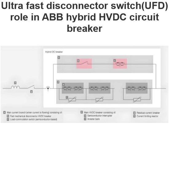
The main path’s UFMS just needs to generate a high enough voltage to commutate the current to the parallel full IGBT breaker. The resistance of the auxiliary DC breaker, Rdson at 2 kA, and the fast mechanical switch need to be less than 20 mW to have similar characteristics as an electromechanical circuit breaker. Utilizing UFMS in the main path results in lower on-state losses and forward voltage than a full SSCB.
The proposed design can be beneficial over the high voltage HCBs manufactured by ABB and Alstom, because (1) there is no on-state semiconductor loss, (2) its control circuit will be simpler, and (3) the expensive “Power Electronic Switch” in the main path, can be avoided. Indeed, only one UFMS can substitute both the “Power Electronic Switch”, and the fast disconnector proposed by ABB for the main path.
However, it needs to ensure that UFMS contact resistance is no more than equivalent electromechanical contacts and has the withstand holding force capability of 4.45×10⁻⁷ I2 N (i.e > 178 N for 10x in-rush at 2 kA rated with safety factor 2x or 356 N).
Ultrafast Mechanical Switch in medium voltage hybrid DC circuit breaker:
The challenges for realizing the mentioned philosophy are (1) whether such ultrafast switches can be developed for MV levels, (2) whether the buildup of the arc voltage for commutation is sufficiently high, and (3) whether the same design is possible for RCB. The answer may be YES for all questions as discussed below.
Electromagnetic Thomson coil (TC) actuators operating based on attractive or repulsive forces between current-carrying conductors are very suitable for fast switching because they can achieve high accelerations through precise control. So far, two techniques based on TC have been proposed and well-elaborated for ultra-fast mechanical switches, where the one with series coils outperformed the one based on induction in terms of efficiency. These two techniques were also compared by Multiphysics finite element modeling.
A single phase 12 kV (nominal voltage) and 2 kA (nominal current) / 20 kA (short circuit) fault-current limiting circuit breaker (FCLCB) and 24 kV, 3 kA / 40 kA FCLCB enabling the arc to be extinguished without any forced arc cooling within 100-300 μs were designed, built.
The induction-based fast switch with a rated current of 7 kA accelerates an HCB contact of ~2 kg with an initial acceleration of ~44,900 m/s2 that results in 4 mm contact separation after ~422 μs, enough to withstand a rated switch voltage of 3 kV .
This fast motion should be damped at the end of travel to prevent over-travel, bounce, fatigue, and other undesirable effects.