Solar Panel – Comprehensive Guide to Solar Cell Selection
A systematic selection reference for photovoltaic engineers and technicians, covering technical principles, key parameters, application scenarios and development trends.
Data baseline: 2024–2025 industrial mass-production levels (CPIA data)
1. The Role of Solar Cells in Photovoltaic Systems
More than 90% of the conversion efficiency and power generation performance of PV modules are determined by solar cells. As the core semiconductor device that directly converts solar radiation into direct current electricity, the technical route, size specifications and quality grade of solar cells directly affect:
- System installed capacity and Levelized Cost of Energy (LCOE)
- Module degradation rate and lifetime power generation
- System balance costs (BOS costs: brackets, inverters, cables, etc.)
- Adaptability to different climates and application scenarios
2. Overview of Mainstream Technical Routes
2.1 Technology Evolution Path
Polycrystalline → Monocrystalline PERC → N-type TOPCon → HJT (Heterojunction) → BC (Back Contact) → Perovskite Tandem (under development)
The market has completed the main shift from P-type to N-type. By the end of 2024, the market share of N-type silicon wafers exceeded 80%. TOPCon has become the absolute mainstream, HJT and BC are ramping up rapidly, and perovskite tandem technology is on the eve of mass production.
Features:
- Optimal temperature coefficient, with outstanding annual power generation advantages in high-temperature regions (northwestern deserts, Southeast Asia)
- Ultra-high bifaciality, suitable for tracking brackets + ground scenarios with high reflectivity
- Low-temperature process causes minimal damage to silicon wafers, allowing the use of thinner wafers (110–130 μm) to further reduce material costs
- High specificity of production equipment, incompatible with existing TOPCon lines, resulting in high capital expenditure for capacity expansion
- The best candidate for bottom cells to integrate with perovskite tandem technology in the future
2.2 Detailed Introduction to Each Technical Route
P-type PERC (Aluminum Back Surface Passivated Emitter and Rear Contact)
| Item |
Parameter |
| Wafer Type |
P-type Monocrystalline Silicon |
| Mass Production Efficiency (2024) |
23.0%~23.5% |
| Theoretical Efficiency Limit |
~24.5% |
| First-year Degradation |
≤2%, ≤0.55%/year from the second year onwards |
| Temperature Coefficient (Pmax) |
−0.35%/°C |
| Bifaciality |
≤75% |
| Manufacturing Cost |
Lowest |
| Technical Maturity |
Extremely high with well-established production lines |
N-type HJT (Heterojunction / Silicon Heterojunction)
| Item |
Parameter |
| Wafer Type |
N-type monocrystalline silicon + amorphous silicon thin film |
| Mass Production Efficiency (2024) |
24.5%~25.5%; leading manufacturers reach over 26% |
| Theoretical Efficiency Limit |
Over 27%; perovskite tandem cell exceeds 30% |
| First-year Degradation |
≤1%, ≤0.25%/year starting from the second year (among the lowest in the industry) |
| Temperature Coefficient (Pmax) |
−0.24%~−0.26%/°C (superior to TOPCon) |
| Bifaciality |
≥90% (up to 98% at maximum) |
| Process Temperature |
≤230°C (much lower than TOPCon’s 960~1050°C) |
| Carbon Emission |
Significantly lower than TOPCon and BC |
Features:
- Boasts the optimal temperature coefficient, delivering outstanding annual power generation advantages in high-temperature regions such as Northwest China’s deserts and Southeast Asia.
- Ultra-high bifaciality makes it ideal for tracking bracket systems and ground sites with high albedo.
- Low-temperature manufacturing process causes minimal damage to silicon wafers, enabling the use of thinner wafers (110~130 μm) to further reduce material costs.
- Highly dedicated production equipment is incompatible with existing TOPCon production lines, resulting in high capital expenditure for capacity expansion.
- It is the best candidate for the bottom cell integrated with perovskite tandem technology in the future.
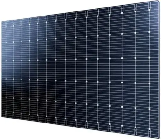
N-type BC (Back Contact Cell)
| Item |
Parameter |
| Silicon Type |
N-type monocrystalline silicon |
| Mass production efficiency (2024) |
23.9% (module); single cell up to 26%+ |
| First-year degradation |
≤1% |
| Temperature coefficient (Pmax) |
−0.29%/°C |
| Bifaciality |
<60% (no grid lines on front; power output from rear) |
| Appearance |
All-black / grid-free, with optimal aesthetics |
Core Logic:
BC is an electrode engineering platform that can be combined with TOPCon (TBC) and HJT (HBC) to further improve efficiency. Aiko ABC (All Back Contact) modules achieved leading mass-production efficiency in 2025, reaching 23.9% at the module level.
Application Scenarios:
- Distributed systems (commercial & industrial / residential rooftops): All-black aesthetic + high power density, with large premium space
- BIPV (Building Integrated Photovoltaics): Grid-free design meets architectural aesthetic requirements
- Utility-scale ground power stations: Low bifaciality is a shortcoming, but performance is rapidly improving with TBC technology iteration
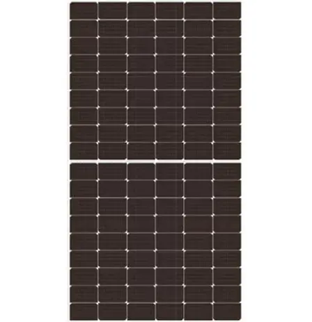
Perovskite and Tandem Cells (Cutting-edge Technology)
| Item |
Parameter |
| Lab efficiency (tandem) |
34%–35% (perovskite/silicon tandem, breakthrough in 2024–2025) |
| Mass production status |
Small-batch trial production; not yet commercially scaled up |
| Theoretical efficiency limit |
Tandem structure up to 46%+ |
Main Challenges:
- Stability (high temperature, UV radiation), lead toxicity (alternative materials under development), and large-area uniformity.
- Mass commercialization is expected from 2026 to 2028.
- It is not considered a primary choice for current selection, but experience from demonstration projects can be monitored.
3. Detailed Explanation of Key Selection Parameters
3.1 Conversion Efficiency (η)
Cell efficiency is the most critical parameter, as it directly determines power generation per unit area and land occupation.
η = Pₘₐₓ / (E × A)
Where:
- Pₘₐₓ = Maximum power at the maximum power point
- E = Irradiance under Standard Test Conditions (STC): 1000 W/m²
- A = Area of the solar cell
Selection Suggestion:
Focus on module efficiency rather than just cell efficiency. Module packaging losses are approximately 2%–3%, and differences in packaging processes among brands cannot be ignored.
3.2 Temperature Coefficient (β-Pmax)
In actual operation, the junction temperature of solar cells far exceeds 25°C under STC, typically reaching 50°C to 70°C. The temperature coefficient determines power loss at high temperatures.
PActual=PSTC×[1+βPmax×(Tcell−25°C)]
| Technology |
Temperature Coefficient (%/°C) |
Efficiency Loss at 60°C |
| PERC |
−0.35 |
−12.25% |
| TOPCon |
−0.30 |
−10.50% |
| BC |
−0.29 |
−10.15% |
| HJT |
−0.25 |
−8.75% |
Conclusion: HJT is the preferred choice for high-temperature regions (Northwest China, Southeast Asia), as it can significantly increase annual power generation.
3.3 Degradation Rate (LID / LETID / Annual Degradation)
The power output of solar cells continues to decline during long‑term operation. Degradation is divided into three types:
- LID (Light Induced Degradation): Significant in P‑type PERC, while almost negligible in N‑type cells.
- LETID (Light and Elevated Temperature Induced Degradation): Additional degradation occurs in PERC under high temperature and illumination.
- Normal Annual Degradation: Related to carrier lifetime and contact passivation quality.
| Technology |
First-year degradation |
Annual degradation (from Year 2) |
Power retention at Year 25 |
| PERC |
≤2.0% |
≤0.55% |
≥83.1% |
| TOPCon |
≤1.0% |
≤0.40% |
≥88.4% |
| HJT |
≤1.0% |
≤0.25% |
≥92.75% |
| BC |
≤1.0% |
≤0.40% |
≥88.4% |
From a full life cycle perspective: the low degradation advantage of HJT can deliver an additional 3%–5% of cumulative power generation over a 25‑year operating period.
3.4 Silicon Wafer Size
Silicon wafer size directly affects module power, BOS cost, and transportation & installation efficiency.
| Size Identifier |
Specification |
Typical Application |
| M6 |
166×166 mm |
Gradually phased out from mainstream use |
| M10 (182) |
182×182 mm |
Current mainstream, balancing power and transportation |
| G12 (210) |
210×210 mm |
Large‑scale ground power stations, high power |
| Rectangular (182×210) |
182×210 mm |
New mainstream in 2024–2025, strongest overall advantages |
Advantages of Rectangular Silicon Wafers (182×210 mm)
- Increase cell area by approximately 15%, with a corresponding increase in module power.
- Optimal container loading efficiency, reducing logistics costs.
- Compatible with both 182 mm and 210 mm production lines, ensuring strong industrial chain synergy.
- Has become the preferred size for new production lines in the industry during 2024–2025.
3.5 Bifaciality Factor
The rear side of bifacial modules can capture ground-reflected irradiance (ground albedo) to improve power generation.
Bifacial Gain ≈ Bifaciality Factor × Ground Albedo × Tilt Coefficient
Typical ground albedo values:Concrete: 0.25, White sand: 0.4, Snow: 0.5–0.8, Grass: 0.2
| Technology |
Bifaciality |
Suitable for Bifacial Gain Scenarios |
| PERC |
≤75% |
Average |
| TOPCon |
≥85% |
Good |
| HJT |
≥90% |
Best |
| BC |
<60% |
Poor (improved in new TBC versions) |
4. Silicon Wafer Types: N-type vs P-type
| Comparison Item |
P-type (PERC) |
N-type (TOPCon/HJT/BC) |
| Base Doping |
Boron (B) |
Phosphorus (P) |
| Minority Carrier Lifetime |
Short (affected by Fe–B pairs) |
Long (no B–O defects) |
| LID |
Obvious |
Almost none |
| Efficiency Potential |
Limited (upper limit ~24.5%) |
Higher (>26%) |
| Production Cost |
Low |
Slightly higher (continuously decreasing) |
| Market Trend |
Shrinking |
Mainstream, market share rising |
For new projects after 2025, a full shift to N‑type cells is recommended unless subject to extreme cost constraints.
5. Selection Guide by Application Scenario
5.1 Large-scale Centralized Ground-mounted Power Station (≥10 MW)
Core Requirements: Maximize LCOE (Levelized Cost of Electricity), focusing on annual power generation, BOS cost and operation & maintenance convenience.
Recommendation Priority:
- N‑type TOPCon + large‑size rectangular silicon wafers (182×210 mm) bifacial modules
- Optimal current cost‑performance ratio, high bifaciality + high efficiency
- Significant benefits with tracking brackets + white sand / concrete ground
- N‑type HJT (for high‑temperature desert regions: Northwest China, Middle East, Southeast Asia)
- Temperature coefficient advantage delivers clear generation gains in hot, high‑irradiance summer conditions
Key Parameter Requirements:
- Module efficiency ≥ 22.5% (N‑type)
- Annual degradation ≤ 0.4%
- Bifaciality ≥ 80%
- 25‑year power warranty: ≥ 83% (PERC) or ≥ 87% (N‑type)
5.2 Commercial & Industrial Rooftop Distributed PV (100 kW ~ 10 MW)
Core Requirements:
High power density (limited rooftop space), safety and reliability, compatibility with building loads.
Recommendations:
- TOPCon 182×210 mm rectangular monofacial / bifacial modules: mainstream choice with excellent overall cost‑performance
- BC modules (for aesthetic or premium scenarios): suitable for corporate headquarters and commercial buildings with high brand image demands
Notes:
- Rooftop load‑bearing verification (large modules weigh 28–35 kg each)
- Fire rating requirements (GB/T 31603)
- Low‑light performance: TOPCon / HJT offer better low‑light response than PERC when shaded near factories
5.3 Residential Rooftops (5–30 kW)
Core Requirements:
Limited installation space, aesthetics, low maintenance, long service life.
Recommendations:
- TOPCon M10 / rectangular high‑efficiency monofacial modules: mainstream standard
- BC all‑black modules (for mid‑to‑high‑end users pursuing aesthetics): 10%–20% premium, suitable for sloped roofs with colored steel / glazed tiles
Size Suggestion:
Residential projects should prioritize 182 mm (M10) for easier handling and installation.
G12 (210 mm) large modules are not recommended.
5.4 BIPV (Building Integrated Photovoltaics)
Core Requirements:
Architectural aesthetics + safety + waterproofing + power generation.
Recommendations:
- BC cells: no grid lines on the front, appearance closest to standard glass
- HJT low‑temperature process: enables colored / transparent BIPV modules
- Silicon wafer size: customized to building modules, flexibility first
Key Standard Reference:
GB/T 51368 Technical Standard for Application of Building Photovoltaic Systems
5.5 Supplementary Special Scenarios
| Application Scenario |
Recommended Technology |
Core Reason |
| Agri-PV (Agricultural Photovoltaic Complementation) |
Bifacial TOPCon |
Adjustable light transmittance with balanced bifacial power gain |
| Floating PV |
HJT / TOPCon |
High ground reflectivity, good heat dissipation and superior temperature coefficient |
| Extreme Plateau Environments |
HJT |
Minimum performance degradation under low-temperature conditions |
| Desert Tracking Power Plants |
Bifacial TOPCon / HJT |
Superimposed benefits of high bifaciality and tracking power gain |
| Mobile / Off-Grid Energy Storage |
High-efficiency small-size TOPCon |
Excellent weight-to-power ratio |
6. Key Quality Inspection Points in Procurement and Selection
6.1 Certifications and Standards
| Standard / Certification |
Description |
| IEC 61215 |
Module design qualification and type approval |
| IEC 61730 |
Module safety qualification |
| IEC 62804 |
PID (Potential Induced Degradation) testing |
| IEC TS 63290 |
Test methods for bifacial modules |
| GB/T 9535 |
Design qualification for terrestrial crystalline silicon modules in China |
| UL 1703 / UL 61730 |
North American market access certification |
Relate News:https://qr.ae/pFt4dJ









 Login