
Search


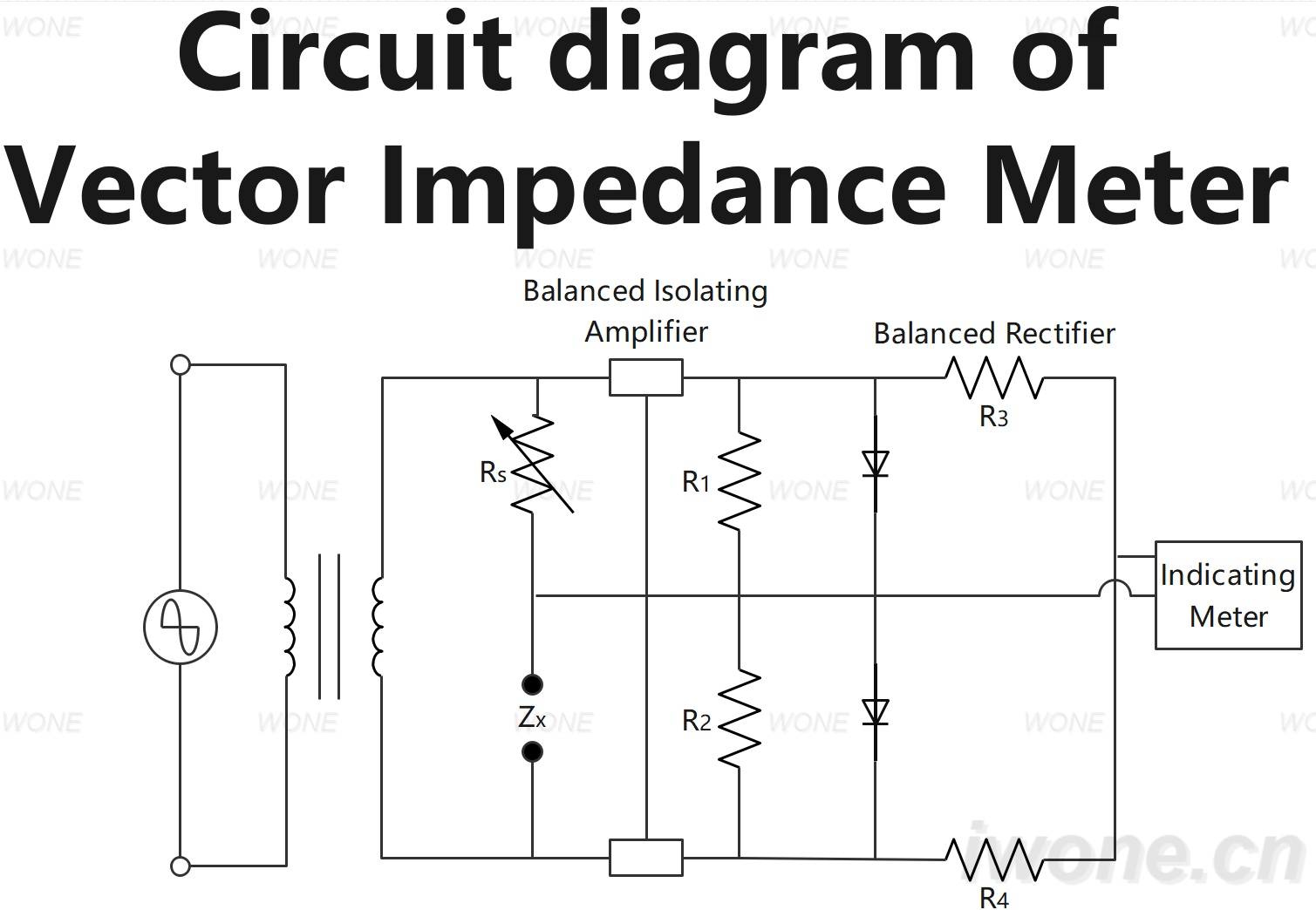
Circuit diagram of Vector Impedance Meter

This article summarizes the Circuit Diagram of Vector Impedance Meter covering its related component connections working principle and functions in measuring impedance magnitude and phase angle.

Master Electrician
Field: Distribution
Power Engineer
10Year<
China
Add us on Google

Circuit diagram of Vector Impedance Meter

屏幕截图 2024-09-10 143057.jpg

Give a tip and encourage the author!

Comments

Share your question or perspective
WhatsApp
Send inquiry
+86
Click to upload file
Download
Get the IEE Business Application
Use the IEE-Business app to find equipment, obtain solutions, connect with experts, and participate in industry collaboration anytime, anywhere—fully supporting the development of your power projects and business.
Login
or continue with
New here?
Register








