• Product
  • Suppliers
  • Manufacturers
  • Solutions
  • Free tools
  • Knowledges
  • Experts
  • Communities
Search


What is Inductance?

The Electricity Forum
Field: Publishes Electricity
0
Canada

What is Inductance?

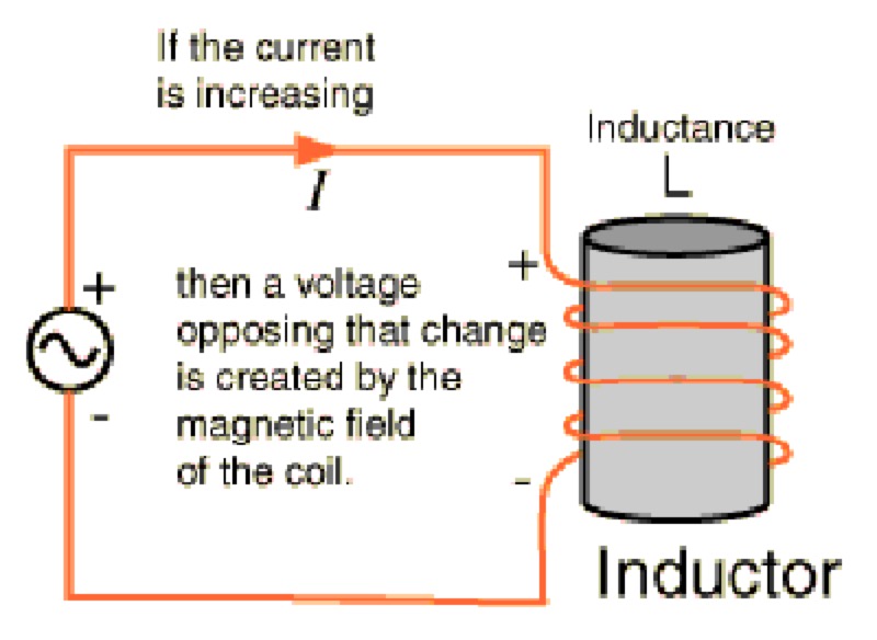
Inductance occurs when a change in current flow is exploited for the purpose of preventing signals with a higher frequency component from passing while allowing signals of lower frequency components to pass. This is why inductors are sometimes referred to as "chokes," since they effectively choke off higher frequencies. A common application of a choke is in a radio amplifier biasing circuit where the collector of a transistor needs to be supplied with a DC voltage without allowing the RF (radio frequency) signal from conducting back into the DC supply.

WechatIMG1541.jpeg

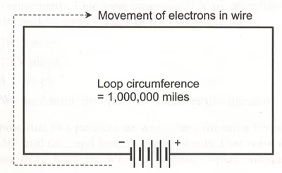
Imagine a wire 1,000,000 miles (about 1,600,000 kilometers) long. Imagine that we make this wire into a huge loop, and then we connect its ends to the terminals of a battery as shown in Figure 1. driving current through the wire.

If we used a short wire for this experiment, the current would begin to flow immediately, amil it would attain a level limited only by the resistance in the wire and the resistance in the battery. But because we have an extremely long wire, the electrons require some time to work their way from dr negative battery terminal, around the loop, and back to the positive terminal. Therefore, it will take so time for the current to build up to its maximum level.

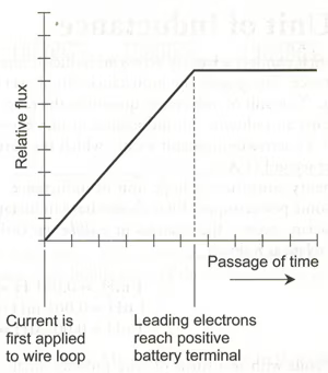
The magnetic field produced by the loop will start out small, during the first few momei when current flows in only part of the loop. The field will build up as the electrons get around th loop. Once the electrons reach the positive battery terminal so that a steady current flows around the entire loop, the magnetic field quantity will attain its maximum and level off, as shown in Figure 2. At that time, we'll have a certain amount of energy stored in the magnetic field. The amount of stored energy will depend on the inductance of the loop, which depends on its overall size. We symbolize inductance, as a property or as a mathematical variable, by writing an italicized, uppercase letter L. Our loop constitutes an inductor. To abbreviate "inductor," we write an upper-case, non-italicized letter L.


WechatIMG1543.png 

Fig. 1. We can use a huge, imaginary loop of wire to illustrate the principle of inductance

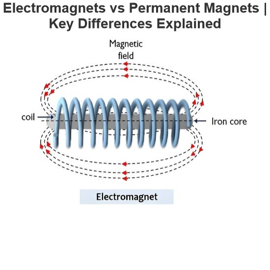
Obviously, we can't make a wire loop measuring anywhere near 1,000,000 miles in circumference. But we can wind fairly long lengths of wire into compact coils. When we do that, the magnetic flux for a given length of wire increases compared with the flux produced by a single-turn loop, increasing the inductance. If we place a ferromagnetic rod called a core inside a coil of wire, we can increase the flux density and raise the inductance even more.

We can attain values of L many times greater with a ferromagnetic core than we can get with a similar-sized coil having an air core, a solid plastic core, or a solid dry wooden core. (Plastic and dry wood have permeability values that differ little from air or a vacuum; engineers occasionally use these materials as coil cores or "forms" in order to add structural rigidity to the windings without significantly changing the inductance.) The current that an inductor can handle depends on the diameter of the wire. But the value of L also depends on the number of turns in the coil, the diameter of the coil, and the overall shape of the coil.

If we hold all other factors constant, the inductance of a helical coil increases in direct proportion to the number of turns of wire. Inductance also increases in direct proportion to the diameter of the coil. If we "stretch out" a coil having a certain number of turns and a certain diameter while holding all other parameters constant, its inductance goes down. Conversely, if we "squash up" an elongated coil while holding all other factors constant, the inductance goes up.

Under normal circumstances, the inductance of a coil (or any other type of device designed to function as an inductor) remains constant regardless of the strength of the signal we apply. In this context, "abnormal circumstances" refer to an applied signal so strong that the inductor wire melts, or the core material heats up excessively. Good engineering sense demands that such conditions should never arise in a well-designed electrical or electronic system.


WechatIMG1544.png 

Fig. 2. Relative magnetic flux in and around a huge loop of wire connected to a current source, as a function of time.

Statement: Respect the original, good articles worth sharing, if there is infringement please contact delete.

Give a tip and encourage the author!
Recommended
Difference Between Electromagnet and Permanent Magnet
Electromagnets vs. Permanent Magnets: Understanding the Key DifferencesElectromagnets and permanent magnets are the two primary types of materials that exhibit magnetic properties. While both generate magnetic fields, they differ fundamentally in how these fields are produced.An electromagnet generates a magnetic field only when an electric current flows through it. In contrast, a permanent magnet inherently produces its own persistent magnetic field once it has been magnetized, without requirin
Edwiin
08/26/2025
Working Voltage in Power System
Working VoltageThe term "working voltage" refers to the maximum voltage that a device can withstand without sustaining damage or burning out, while ensuring the reliability, safety, and proper operation of both the device and associated circuits.For long-distance power transmission, the use of high voltage is advantageous. In AC systems, maintaining a load power factor as close to unity as possible is also economically necessary. Practically, heavy currents are more challenging to handle than hi
Encyclopedia
07/26/2025
What is a Pure Resistive AC Circuit?
Pure Resistive AC CircuitA circuit containing only a pure resistanceR(in ohms) in an AC system is defined as a Pure Resistive AC Circuit, devoid of inductance and capacitance. Alternating current and voltage in such a circuit oscillate bidirectionally, generating a sine wave (sinusoidal waveform). In this configuration, power is dissipated by the resistor, with voltage and current in perfect phase—both reaching their peak values simultaneously. As a passive component, the resistor neither
Edwiin
06/02/2025
What is a Pure Capacitor Circuit?
Pure Capacitor CircuitA circuit comprising only a pure capacitor with capacitanceC(measured in farads) is termed a Pure Capacitor Circuit. Capacitors store electrical energy within an electric field, a characteristic known ascapacitance(alternatively referred to as a "condenser"). Structurally, a capacitor consists of two conductive plates separated by a dielectric medium—common dielectric materials include glass, paper, mica, and oxide layers. In an ideal AC capacitor circuit, the current
Edwiin
06/02/2025
Seed Inquiry
Download
Get the IEE Business Application
Use the IEE-Business app to find equipment, obtain solutions, connect with experts, and participate in industry collaboration anytime, anywhere—fully supporting the development of your power projects and business.