• Product
  • Suppliers
  • Manufacturers
  • Solutions
  • Free tools
  • Knowledges
  • Experts
  • Communities
Search


What should be noted when using indoor vacuum circuit breakers?

Echo
Echo
Field: Transformer Analysis
China

I. Overvoltage Prevention

Vacuum circuit breakers excel in interrupting performance, but high overvoltage may occur across inductors during the switching of inductive loads due to abrupt changes in loop current, which requires special attention. When switching small-capacity motors, starting currents are large, so measures like step-down starting should be adopted to limit the current.

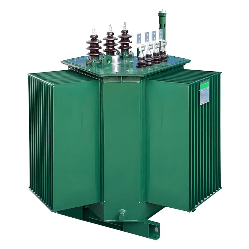
Transformers with different structures show distinct characteristics: oil-immersed transformers have high impulse voltage withstand capability and large stray capacitance, eliminating the need for additional protection; dry-type transformers with low impulse voltage resistance should preferably be protected by zinc oxide arresters, or by utilizing cable distributed capacitance and installing capacitors.

For outgoing line protection vacuum circuit breakers, long lines and large stray capacitance, combined with multiple connected devices, generally prevent the generation of high trapped-phenomenon overvoltage, so no special protection is needed during operation.

Field tests on capacitor banks show that the overvoltage generated by vacuum circuit breakers during switching typically does not exceed twice the rated value. In China, shunt capacitors are commonly used below 60kV, where equipment insulation levels are high enough to withstand normal switching overvoltage. However, poor-performance circuit breakers may cause high overvoltage due to prolonged contact vibration during switching, as evidenced by domestic and international test cases, which demands vigilance.

II. Control of Closing and Opening Speeds

A too-low closing speed prolongs pre-breakdown time, increasing contact wear. Vacuum circuit breaker interrupters, often using copper brazing and high-temperature degassing, have limited mechanical strength and vibration resistance. Excessively high closing speed causes severe vibration and bellows impact, drastically shortening the bellows service life. Typically, the closing speed should be controlled at 0.6m/s–2m/s, with an optimal value for specific structures that requires precise adjustment.

During interruption, the arc duration is short (no more than 15 power frequency half-waves), and the interrupter must have sufficient insulation strength at the first current zero-crossing. It is generally desired that the contact stroke reaches 50%–80% of the full stroke within one power frequency half-wave, necessitating strict control of the opening speed. Additionally, the opening and closing buffers should have excellent characteristics to mitigate impact forces and protect the interrupter lifespan.

III. Contact Stroke Control

Vacuum circuit breakers feature short contact strokes (typically 8mm–12mm for 10kV–15kV rated voltage, with an over-travel of only 2mm–3mm). Do not mistakenly increase the stroke under the assumption that a larger gap benefits arc extinction. Excessive stroke will impose excessive stress on the bellows after closing, causing damage and compromising the vacuum seal, which may lead to equipment failure.

IV. Load Current Limitation

Vacuum circuit breakers have poor overload capacity. The vacuum between contacts and the housing forms thermal insulation, so heat from contacts and conductive rods mainly dissipates through conduction. To keep the operating temperature within the allowable range, the working current must be strictly limited to below the rated value to avoid overheating and ensure reliability.

V. Stringent Handover and Acceptance

Although vacuum circuit breakers undergo rigorous factory acceptance, transportation and installation may alter parameters or cause mechanism mismatches. After on-site installation, key parameters must be retested, including closing bounce, opening distance, compression stroke, closing/opening speeds and times, contact resistance, break insulation level, and transmission acceptance tests, to ensure all indicators meet technical requirements.

VI. Maintenance Cycle Implementation

Vacuum circuit breakers are not maintenance-free; the cycle should be adjusted flexibly based on regulations and actual operation:

  • During seasonal (annual) preventive tests, use power frequency withstand voltage to inspect the vacuum degree of interrupter breaks and ensure arc extinction performance.

  • After 2,000 normal operations (load current switching) or 10 rated short-circuit current interruptions, check all screws and verify parameters against maintenance specifications; continue use if qualified.

  • After 20 years of out-of-service storage or transportation, retest the vacuum degree according to interrupter inspection standards and replace the device if unqualified.

VII. Vacuum Interrupter Maintenance

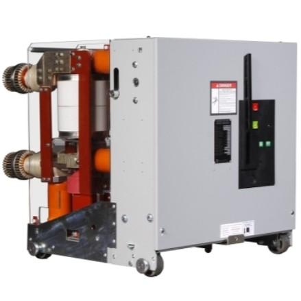
The vacuum interrupter, the core component, uses glass or ceramic for support and sealing, with moving/stationary contacts and a shield inside, maintaining a vacuum degree of 1.33×10⁻⁵Pa to ensure arc extinction and insulation. A decrease in vacuum degree significantly impairs interrupting performance, so avoid any external collision, knocking, or impact during handling and maintenance. Prohibit placing objects on the circuit breaker to prevent interrupter damage from falls.

After strict parallelism inspection and assembly at the factory, evenly tighten interrupter bolts during maintenance to ensure uniform force and optimal operation.

The above content, summarized from practical maintenance experience, aims to provide technical references for the safe and reliable operation of indoor vacuum circuit breakers, contributing to improved substation equipment management.

Give a tip and encourage the author!
Recommended
3D Wound-Core Transformer: Future of Power Distribution
Technical Requirements and Development Trends for Distribution Transformers Low losses, especially low no-load losses; highlighting energy-saving performance. Low noise, particularly during no-load operation, to meet environmental protection standards. Fully sealed designto prevent transformer oil from contacting external air, enabling maintenance-free operation. Integrated protection devices within the tank, achieving miniaturization; reducing transformer size for easier on-site installation. C
Echo
10/20/2025
Reduce Downtime with Digital MV Circuit Breakers
Reduce Downtime with Digitized Medium-Voltage Switchgear and Circuit Breakers"Downtime" — it’s a word no facility manager wants to hear, especially when it’s unplanned. Now, thanks to next-generation medium-voltage (MV) circuit breakers and switchgear, you can leverage digital solutions to maximize uptime and system reliability.Modern MV switchgear and circuit breakers are equipped with embedded digital sensors that enable product-level equipment monitoring, providing real-time insights into the
Echo
10/18/2025
One Article to Understand the Contact Separation Stages of a Vacuum Circuit Breaker
Vacuum Circuit Breaker Contact Separation Stages: Arc Initiation, Arc Extinction, and OscillationStage 1: Initial Opening (Arc Initiation Phase, 0–3 mm)Modern theory confirms that the initial contact separation phase (0–3 mm) is critical to the interrupting performance of vacuum circuit breakers. At the beginning of contact separation, the arc current always transitions from a constricted mode to a diffused mode—the faster this transition, the better the interruption performance.Three measures c
Echo
10/16/2025
Advantages & Applications of Low-Voltage Vacuum Circuit Breakers
Low-Voltage Vacuum Circuit Breakers: Advantages, Application, and Technical ChallengesDue to their lower voltage rating, low-voltage vacuum circuit breakers have a smaller contact gap compared to medium-voltage types. Under such small gaps, transverse magnetic field (TMF) technology is superior to axial magnetic field (AMF) for interrupting high short-circuit currents. When interrupting large currents, the vacuum arc tends to concentrate into a constricted arc mode, where localized erosion zones
Echo
10/16/2025
Send inquiry
Download
Get the IEE Business Application
Use the IEE-Business app to find equipment, obtain solutions, connect with experts, and participate in industry collaboration anytime, anywhere—fully supporting the development of your power projects and business.