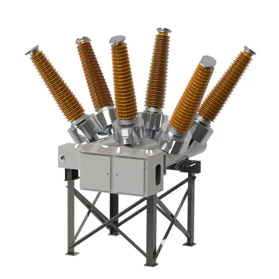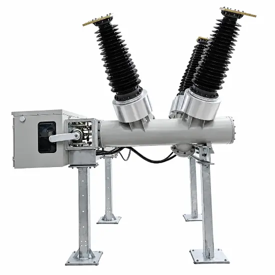
| Marque | ROCKWILL |
| Série | RHD |
| Entrez le contenu que vous souhaitez traduire. | 72.5kV |
| Rated maximum current | 2000~3150 A |
| Lightning impulse withstand voltage | 325/375 |
| Rated short-circuit breaking current | 31.5~50 kA |
| Rated frequency | 50/60 Hz |
Description
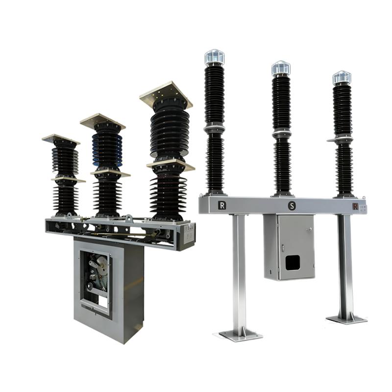
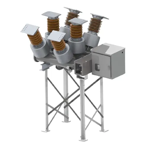
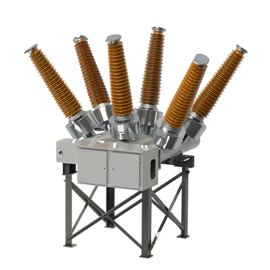
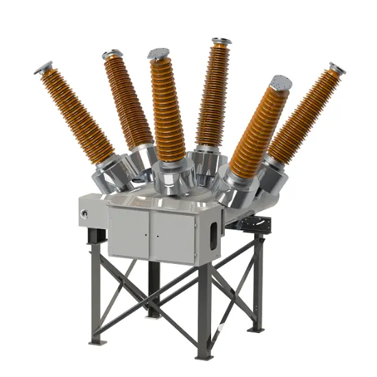
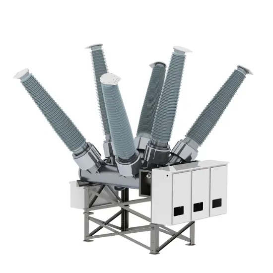
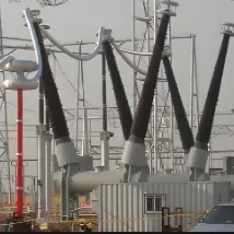
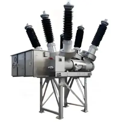
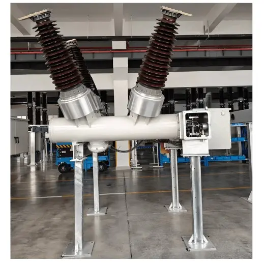
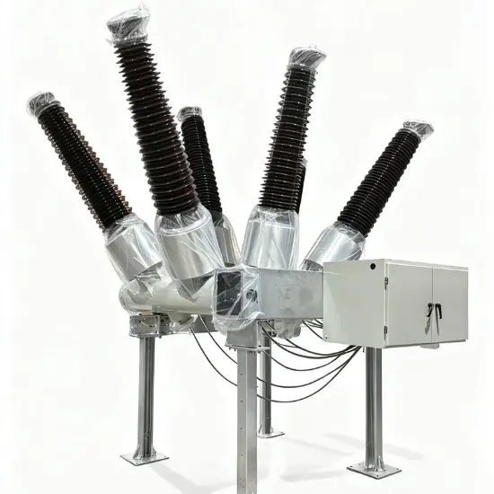
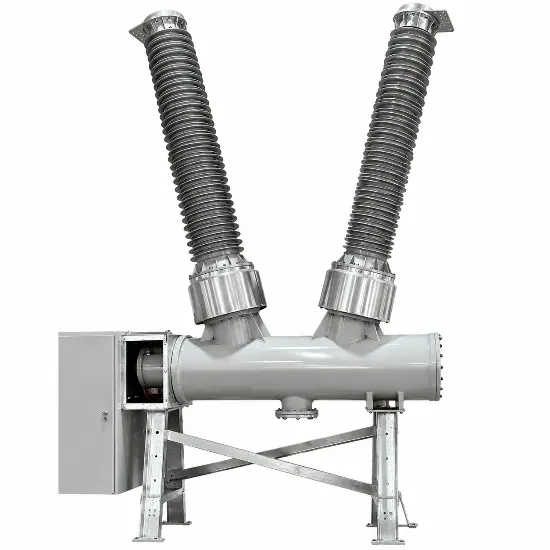
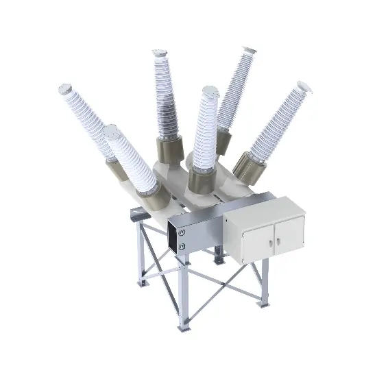
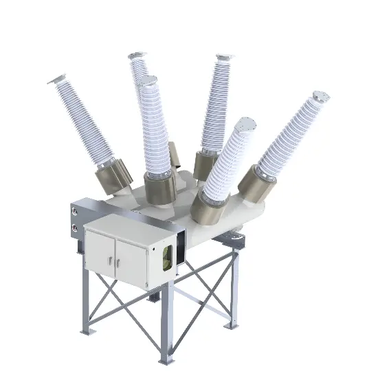
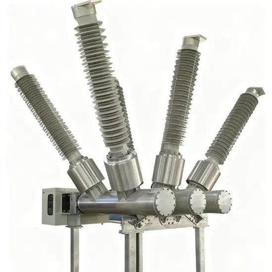
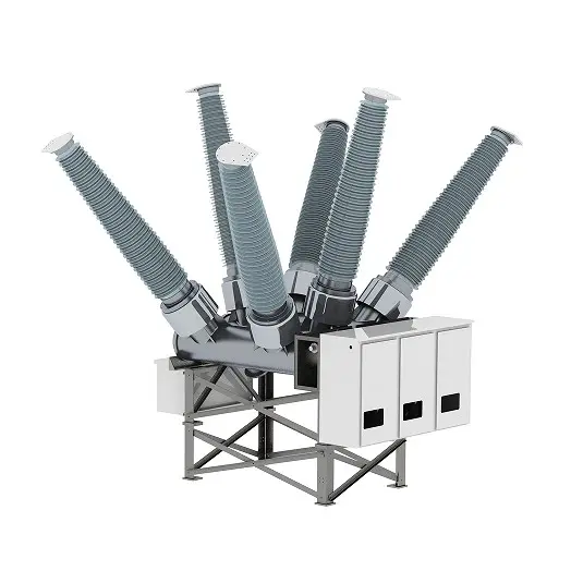
69kV 72.5kV 84kV 88kV Three-phase AC Dead tank type SF6 circuit breaker is suitable for the rated voltage of 66kV, the rated frequency of 50Hz of the high-voltage transmission and transformation system, through the distribution and combined load current, interrupt the fault current, to achieve the control, measurement and protection of the transmission line, the product structure is compact, the area is small, especially suitable for earthquake-prone areas, polluted areas and areas with relatively small space size. The circuit breaker has excellent breaking performance, and the rated short-circuit breaking current can reach 63kA; The product is easy to install and maintain.
Main Features
System Architecture
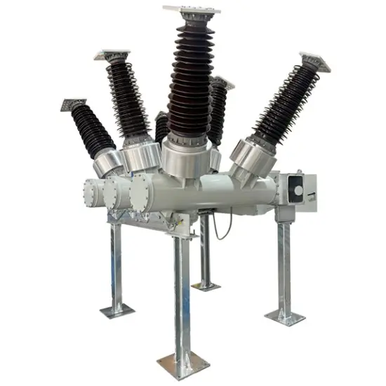
The gas-insulated metal composite combined electrical appliance (HGIS) is composed of several standard functional modules, such as circuit breaker GCB (single and double busbars), isolation-grounding switch TPS, voltage transformer PT, current transformer CT, etc. These modules have the same interface form and size. Various modules can be combined to meet the design and layout requirements of various substations.
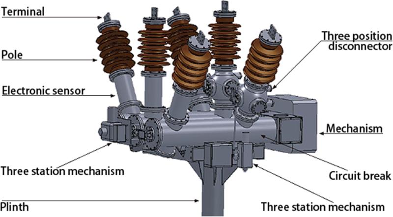
Single-busbar single-isolation scheme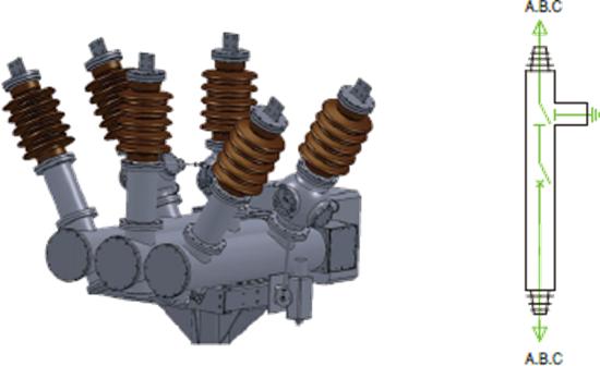
Single-busbar double -isolation scheme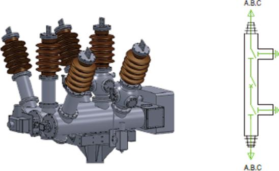
Main characteristics:
electrical
Voltage Ratings: 3.6kV, 4.76kV, 7.2kV, 8.25kV, 11kV, 12kV, 13.2kV, 13.8kV, 15kV, 15.5kV, 17.5kV, 22kV, 22.9kV, 24kV, 25.8kV, 27kV, 33kV, 36kV, 38kV, 40.5kV, 44kV, 60kV, 63kV, 66kV, 69kV, 88kV, 115kV, 123kV, 125kV, 126kV, 132kV, 138kV, 145kV, 150kV, 170kV, 184kV, 204kV, 220kV, 225kV, 230kV, 245kV, 275kV, 330kV, 345kV, 400kV, 765kV, 800kV with a rated short-circuit breaking current of 50kA or 63kA, and we offer customization services.
| Item | Unit | Parameters | |||
| Rated maximum voltage | kV | 72.5 | |||
| Rated maximum current | A | 1600/2500/3150/4000 | |||
| Rated frequency | Hz | 50/60 | |||
| 1min Power frequency withstand voltage | kV | 185 | |||
| Lightning impulse withstand voltage | kV | 450 | |||
| First open pole factor | 1.5/1.5/1.3 | ||||
| Rated short circuit breaking current | kA | 25/31.5/40/50/63 | |||
| Rated short - circuit duration | s | 4/3 | |||
| Rated out - of - phase breaking current | 10 | ||||
| Rated cable charging current | 10/50/125 | ||||
| Rated peak value withstand current | kA | 80/100/125 | |||
| Rated making current (peak) | kA | 80/100/125 | |||
| Creepage distance | mm/kV | 25 - 31 | |||
| SF6 gas leakage rate (per year) | ≤1% | ||||
| Rated SF6 gas pressure(20℃ gauge pressure) | Mpa | 0.5 | |||
| Alarm/blocking pressure(20℃ gauge pressure) | Mpa | 0.45 | |||
| SF6 annual gas leakage rate | ≤0.5 | ||||
| Gas moisture content | Ppm(v) | ≤150 | |||
| Heater voltage | AC220/DC220 | ||||
| Voltage of control circuit | DC | DC110/DC220/DC230 | |||
| Voltage of energy - store motor | V | DC 220/DC 110/AC 220/DC230 | |||
| Applied standards | GB/T 1984/IEC 62271 - 100 | ||||
mechanical
| Name | unit | Parameters | |||
| Opening time | ms | 27±3 | |||
| Closing time | ms | 90±9 | |||
| Minute and conjunction time | ms | 300 | |||
| Together--ivide the time | ms | ≤60 | |||
| Simultaneity of opening | ms | ≤3 | |||
| Closing simultaneity | ms | ≤5 | |||
| Moving contact stroke | mm | 150+2-4 | |||
| Contact contact stroke | mm | 27±4 | |||
| Opening speed | m/s | 4.5±0.5 | |||
| Closing speed | m/s | 2.5±0.4 | |||
| Mechanical life | times | 6000 | |||
| Operation sequence | O - 0.3s - CO - 180s - CO | ||||
| Note: The opening and closing speed and time are the characteristic values of the circuitbreaker when it is single divided and closed under rated conditions. The closing speed is theaverage speed of the moving contact from the rigid closing point to 10 ms before closing, andthe opening speed is the average speed of the moving contact within 10 ms from the justequinox to 10 ms after the separation. | |||||
Product use environment
Place of use: outdoor.
Ambient air temperature: -40℃~ +40℃
Altitude: no more than 1000m.
Air pollution level: Class IV.
Wind pressure: not more than 700Pa (equivalent to wind speed 34 m/s).
Earthquake level: no more than 9 degrees.
Relative humidity: the average daily relative humidity is not more than 95%; The average monthly relative humidity is not more than 90%.
Note: When the use conditions of the circuit breaker exceed the above provisions, it shall be determined by the user and the manufacturer through negotiation.
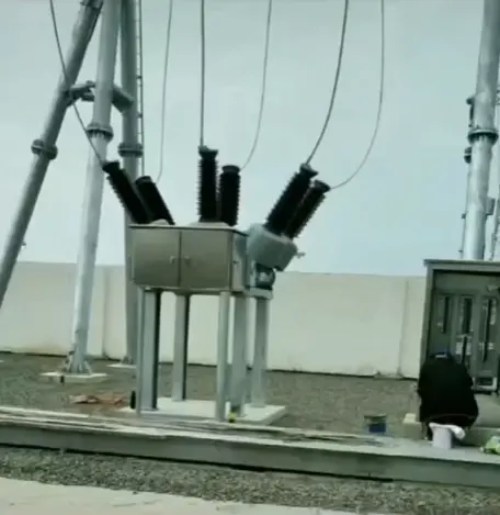
1. Sélectionnez l'interrupteur à disjoncteur correspondant au niveau de tension en fonction du niveau du réseau électrique
La tension standard (40,5/72,5/126/170/245/363/420/550/800/1100 kV) est associée à la tension nominale correspondante du réseau électrique. Par exemple, pour un réseau de 35 kV, un disjoncteur de 40,5 kV est sélectionné. Selon des normes telles que GB/T 1984/IEC 62271-100, la tension nominale est garantie d'être ≥ la tension maximale de service du réseau électrique.
2. Scénarios d'application pour la tension non standard personnalisée
La tension non standard personnalisée (52/123/230/240/300/320/360/380 kV) est utilisée pour des réseaux électriques spéciaux, tels que la rénovation des anciens réseaux et des scénarios industriels spécifiques. En raison de l'absence de tensions standards appropriées, les fabricants doivent personnaliser en fonction des paramètres du réseau, et après la personnalisation, les performances d'isolation et d'extinction d'arc doivent être vérifiées.
3. Les conséquences d'une mauvaise sélection du niveau de tension
Le choix d'un niveau de tension inférieur peut entraîner une rupture d'isolation, conduisant à une fuite de SF et à des dommages aux équipements ; le choix d'un niveau de tension supérieur augmente considérablement les coûts, augmente la difficulté d'exploitation et peut également entraîner des problèmes de compatibilité des performances.








 Connexion