| Thương hiệu | ROCKWILL |
| Chuỗi | RHD |
Product Overview
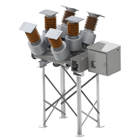
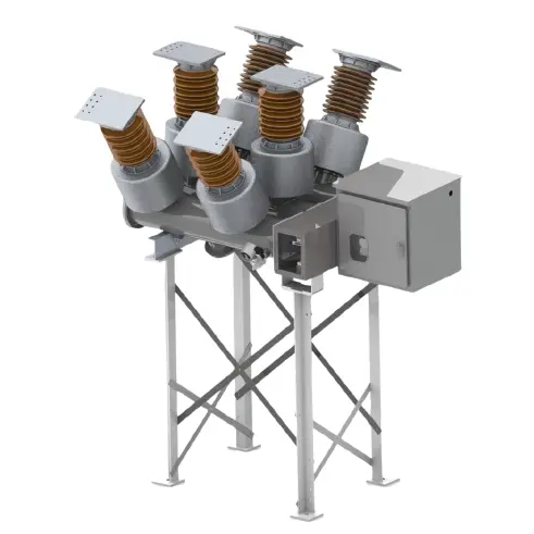
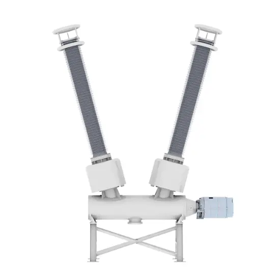
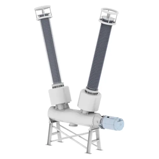
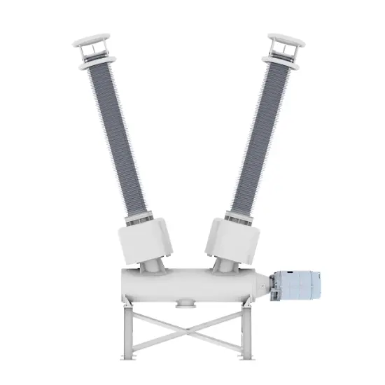
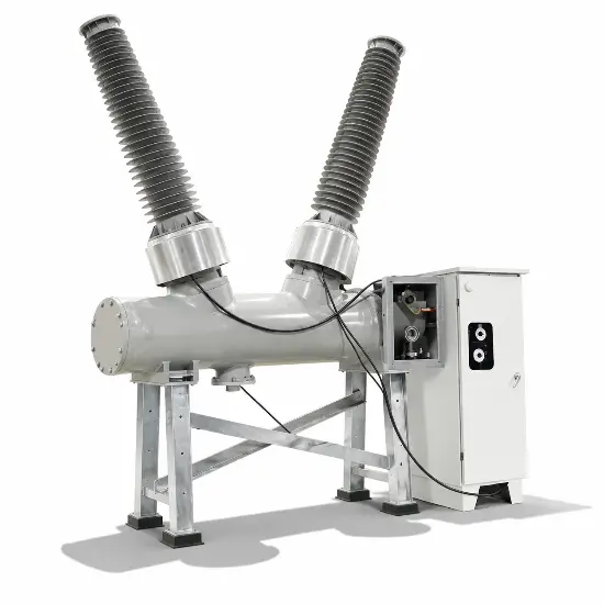
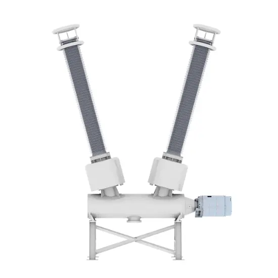
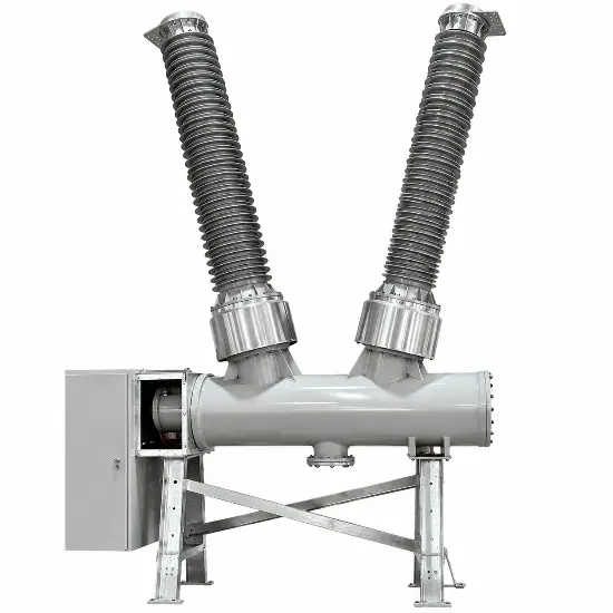
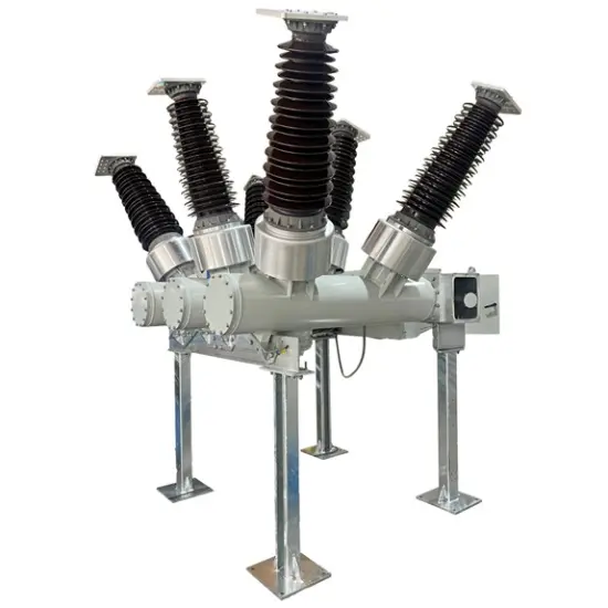
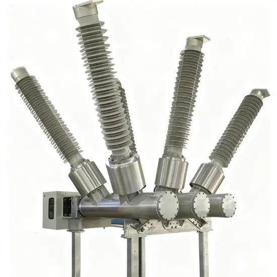
The RHD Series Dead-Tank SF6 Circuit Breaker is engineered for 'customized high-voltage power system solutions', covering standard voltage grades from RHD-40.5 to RHD-550 and supporting 'non-standard voltage customization' to precisely match your unique grid upgrade or construction needs. As a dead-tank type, its grounded tank isolates high-voltage components, ensuring superior insulation performance and safety--making it the go-to choose for demanding high-voltage scenarios.
About customization
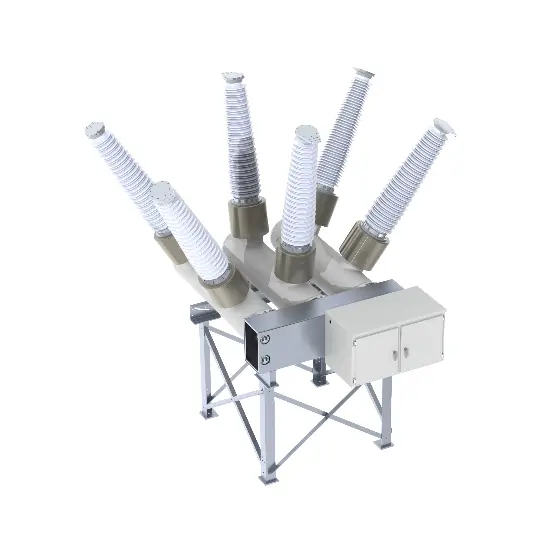
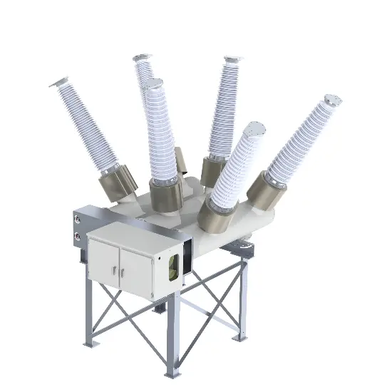
We offer full customization services for voltage classes, including single-phase, two-phase, and three-phase configurations, as well as non-standard voltage/current solutions. Examples of available voltage and current specifications include 1250 A 75 kV, 3200 A 46 kV, 60 kV, 69 kV, and 75 kV (we support customization ranging from 10 kV to 800 kV for voltage and 1250 A to 6300 A for current). Regardless of your power grid's voltage specifications, we tailor the circuit breaker for seamless integration.
All products are fully assembled and tested at our factory before being shipped directly to your site--no disassembly of key components is required. This eliminates the need for on-site high-voltage testing, significantly saving you time and costs.
Key features
1. Superior Seismic Resistance
Adopting a low-center-of-gravity design, the breaker can withstand an earthquake intensity of up to 9 degrees, ensuring stable performance in seismic-prone areas--consistent with the RHD series' proven anti-seismic capability.
2. Excellent Arc-Extinguishing Performance & Long Service Life
Leveraging the high arc-extinguishing efficiency of SF6 gas, the breaker achieves a rated short-circuit breaking current of ≥50kA. It boasts an electrical life of more than 20 operations and a mechanical life of up to 10,000 cycles, significantly reducing equipment replacement and maintenance costs.
3. Low SF6 Gas Leakage Rate
The hermetic metal tank structure minimizes SF6 gas leakage, with an annual leakage rate of ≤1%--far below industry averages. This design not only avoids safety hazards from gas leakage but also reduces environmental impact.
4. Modular Design & Flexible Expansion
It supports on-demand configuration of built-in current transformers (CTs), with up to 15 CTs available for measurement or protection purposes. The standardized module interface allows flexible combination to meet diverse substation design and layout requirements, especially suitable for space-constrained scenarios.
5. Strong Environmental Adaptability
The breaker operates stably in extreme conditions: ambient temperature ranging from -40℃ to +55℃, maximum daily temperature difference of 32K, altitude up to 3,000m, and air pollution level up to Class IV. It also resists wind pressure of 700Pa (equivalent to 34m/s wind speed) and icing thickness of up to 20mm.
6. Comprehensive Safety Protection
Equipped with anti-mis operation interlocking devices, it effectively prevents accidents caused by incorrect operations. Before delivery, the breaker undergoes lightning impulse tests to eliminate insulation discharge risks from production and assembly, ensuring reliable quality.
7. Maintenance-Free Operating Mechanism
It adopts a spring-operated mechanism that is oil-free, gas-free, and maintenance-free. This mechanism delivers stable performance, low noise, and high reliability, reducing long-term operational workload.
Technology Parameters
| Item | Unit | Parameters | |||
| customization of Rated Voltage | kV | 3.6 kV/4.76 kV/7.2 kV/8.25 kV/12 kV /13.2 kV/11kV/12kV/13.8kV/15kV/15.5 kV /17.5 kV/22kV/22.9 kV/24 kV/25.8 kV/27 kV/33kV/36 kV/38 kV/40.5 kV/44kV/60kV/63kV/66kV/69kV/88kV/115kV/123kV/125kV/126kV/132kV/138kV/145kV/ 150kV/170kV/184kV/204kV/220kV/225kV/230kV/245kV/275kV/330kV/345kV/400kV/765kV/800kV |
|||
| customization of Rated current | A | 1250 to 6300 | |||
| Rated frequency | Hz | 50/60 | |||
| 1min Power frequency withstand voltage | kV | Max to 750 | |||
| Lightning impulse withstand voltage | kV | Max to 1675 | |||
| First open pole factor | 1.5/1.3/1.55 | ||||
| Rated short circuit breaking current | kA | 16 to 63 | |||
| Rated short - circuit duration | s | 4,3 | |||
| Rated out - of - phase breaking current | 10 | ||||
| Rated cable charging current | 10/50/125 | ||||
| Rated peak value withstand current | kA | 80/100/125 | |||
| Rated making current (peak) | kA | 80/100/125 | |||
| Creepage distance | mm/kV | 25 - 31 | |||
| SF6 gas leakage rate (per year) | ≤1% | ||||
| Rated SF6 gas pressure(20℃ gauge pressure) | Mpa | 0.5/0.4,0.5,0.6 | |||
| Alarm/blocking pressure(20℃ gauge pressure) | Mpa | 0.45/0.4,0.35/0.33,0.45/0.40,0.55/0.50 | |||
| SF6 annual gas leakage rate | ≤0.5 | ||||
| Gas moisture content | Ppm(v) | ≤150 | |||
| Heater voltage | AC220/DC220 | ||||
| Voltage of control circuit | DC | DC110/DC220/DC230 | |||
| Voltage of energy - store motor | V | DC 220/DC 110/AC 220/DC230 | |||
| Applied standards | GB/T 1984/IEC 62271 - 100 | ||||
| Name | unit | Parameters | |||
| Opening time | ms | 27±3 | |||
| Closing time | ms | 90±9 | |||
| Minute and conjunction time | ms | 300 | |||
| Together--ivide the time | ms | ≤60 | |||
| Simultaneity of opening | ms | ≤3 | |||
| Closing simultaneity | ms | ≤5 | |||
| Moving contact stroke | mm | 150+2-4 | |||
| Contact contact stroke | mm | 27±4 | |||
| Opening speed | m/s | 4.5±0.5 | |||
| Closing speed | m/s | 2.5±0.4 | |||
| Mechanical life | times | 6000 | |||
| Operation sequence | O - 0.3s - CO - 180s - CO | ||||
| Note: The opening and closing speed and time are the characteristic values of the circuitbreaker when it is single divided and closed under rated conditions. The closing speed is theaverage speed of the moving contact from the rigid closing point to 10 ms before closing, andthe opening speed is the average speed of the moving contact within 10 ms from the justequinox to 10 ms after the separation. | |||||
Application Scenarios
Large Hub Substations
Ideal for 220kV+ key hub substations, the customized RHD breaker controls and protects main power circuits. Its non-standard voltage adaptability ensures seamless integration into existing or upgraded grid architecture.
New Energy Grid-Connection Systems
Suitable for high-voltage grid connections in wind and solar power bases. Custom voltage ratings ensure reliable integration of renewable energy into the main grid, even in projects with unique voltage requirements.
Industrial High-Voltage Power Systems
Perfect for heavy industries (metallurgy, chemicals) with specialized voltage needs. The breaker’s robust performance and customizability guarantee stable power supply for high-power industrial equipment.
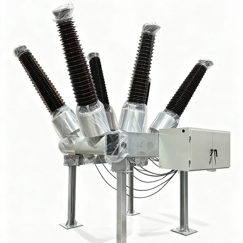
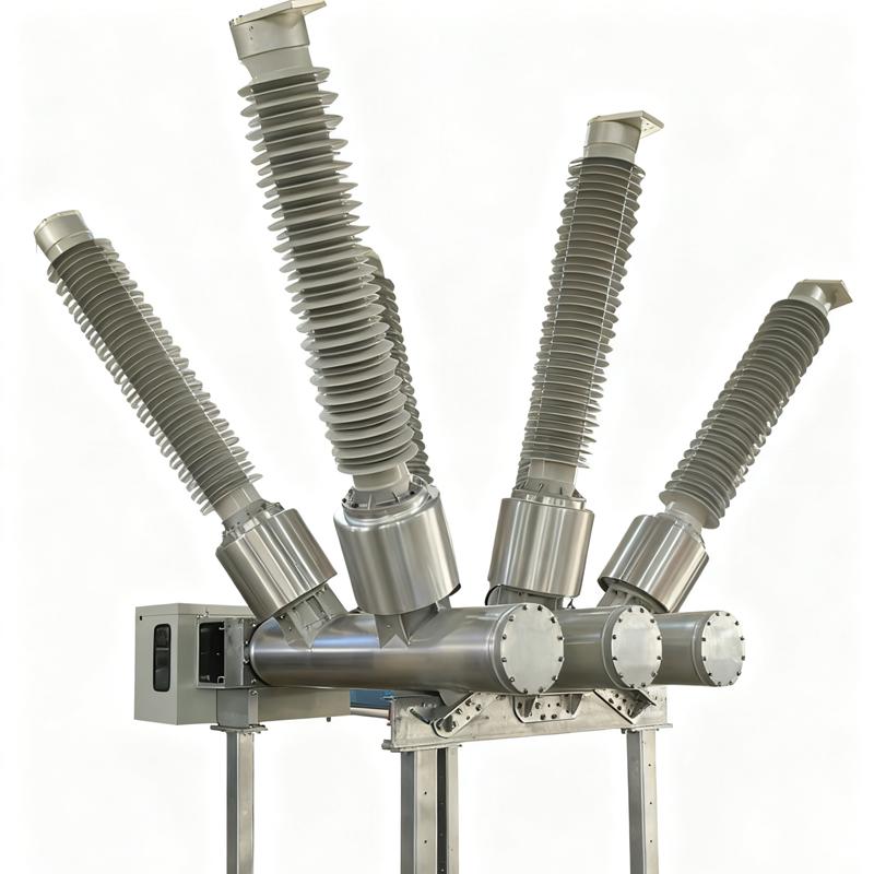
Cấu trúc Thùng Tích hợp: Phòng dập hồ quang, môi trường cách điện và các thành phần liên quan được niêm phong bên trong một thùng kim loại chứa khí cách điện (như hexafluorua sunfur) hoặc dầu cách điện. Điều này tạo thành một không gian tương đối độc lập và kín, ngăn chặn hiệu quả các yếu tố môi trường bên ngoài ảnh hưởng đến các thành phần bên trong. Thiết kế này tăng cường hiệu suất cách điện và độ tin cậy của thiết bị, phù hợp cho nhiều môi trường ngoài trời khắc nghiệt.
Bố cục Phòng Dập Hồ Quang: Phòng dập hồ quang thường được lắp đặt bên trong thùng. Cấu trúc của nó được thiết kế để gọn gàng, cho phép dập hồ quang hiệu quả trong không gian hạn chế. Tuỳ thuộc vào các nguyên lý và công nghệ dập hồ quang khác nhau, cấu trúc cụ thể của phòng dập hồ quang có thể thay đổi, nhưng nói chung bao gồm các thành phần chính như tiếp điểm, vòi phun và vật liệu cách điện. Các thành phần này cùng làm việc để đảm bảo hồ quang được dập nhanh chóng và hiệu quả khi cầu chì ngắt dòng điện.
Mechanism Hoạt động: Các cơ chế hoạt động phổ biến bao gồm cơ chế hoạt động bằng lò xo và cơ chế hoạt động bằng thủy lực.
Cơ chế Hoạt động Bằng Lò Xo: Cơ chế này có cấu trúc đơn giản, độ tin cậy cao và dễ bảo trì. Nó điều khiển các hoạt động đóng và mở của cầu chì thông qua việc lưu trữ và giải phóng năng lượng từ lò xo.
Cơ chế Hoạt động Bằng Thủy Lực: Cơ chế này mang lại lợi ích như công suất đầu ra cao và hoạt động mượt mà, phù hợp cho các cầu chì có điện áp và dòng điện lớn.
1. Chọn cầu chì tương ứng với mức điện áp dựa trên cấp độ lưới điện
Điện áp tiêu chuẩn (40,5/72,5/126/170/245/363/420/550/800/1100kV) được ghép nối với điện áp định mức tương ứng của lưới điện. Ví dụ, cho lưới điện 35kV, chọn cầu chì 40,5kV. Theo các tiêu chuẩn như GB/T 1984/IEC 62271-100, điện áp định mức phải đảm bảo ≥ điện áp hoạt động tối đa của lưới điện.
2. Các tình huống áp dụng cho điện áp tùy chỉnh không theo tiêu chuẩn
Điện áp tùy chỉnh không theo tiêu chuẩn (52/123/230/240/300/320/360/380kV) được sử dụng cho các lưới điện đặc biệt, chẳng hạn như cải tạo lưới điện cũ và các kịch bản công nghiệp điện cụ thể. Do thiếu điện áp tiêu chuẩn phù hợp, nhà sản xuất cần tùy chỉnh theo các thông số của lưới điện, và sau khi tùy chỉnh, phải xác minh hiệu suất cách điện và dập hồ quang.
3. Hậu quả của việc chọn sai mức điện áp
Chọn mức điện áp thấp có thể gây ra sự cố cách điện, dẫn đến rò rỉ SF và hư hỏng thiết bị; Chọn mức điện áp cao làm tăng đáng kể chi phí, tăng khó khăn trong vận hành và có thể cũng dẫn đến vấn đề không khớp về hiệu suất.








 Đăng nhập