Single-Core Shielded Thin-Wall High-Voltage Cable Solution
- Abstract
This solution addresses common industry challenges such as physical damage, chemical corrosion, and electromagnetic interference faced by high-voltage cables in complex environments. The core of the solution is a novel single-core shielded thin-wall high-voltage cable. Through innovative double-layer XLPE protection, a composite shielding structure, and an optional optimized outer sheath design, it delivers exceptional mechanical protection, insulation performance, shielding effectiveness, and an extended service life, providing safe, reliable, and efficient connectivity for power transmission systems.
II. Technical Background and Utility Model Purpose
- Technical Background
Wires and cables, as core fundamental products for transmitting power, conveying information, and enabling electromagnetic energy conversion, are often referred to as the "blood vessels" and "nerves" of the national economy. Their reliability is directly critical to the stable operation of entire systems. However, existing high-voltage cables commonly face severe challenges:
• Biological and Environmental Erosion: Susceptible to damage from rodents, insects, or external moisture, acids, alkalis, and other chemicals, potentially leading to insulation failure, short circuits, or even fire hazards.
• Mechanical Damage: Under conditions such as installation pulling, wind, and sun exposure, the outer insulation layer is prone to wear and cracking, exposing the core and compromising power transmission while posing safety risks.
• Inadequate Shielding: Suboptimal electromagnetic shielding makes the cables vulnerable to external interference or radiation, affecting signal quality and transmission stability. - Utility Model Purpose
This solution aims to provide a single-core shielded thin-wall high-voltage cable with an ingeniously rational structural design, excellent protective performance, long service life, and superior shielding capabilities, thoroughly addressing the aforementioned existing problems and meeting stringent requirements for various complex application scenarios.
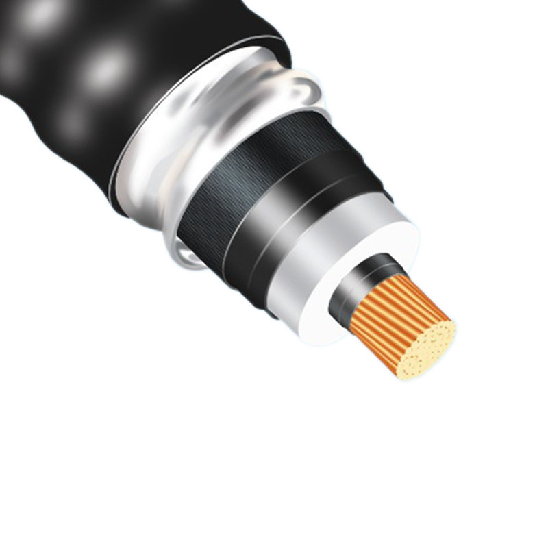
III. Core Cable Structure and Technical Parameters
The cable adopts a precision multi-layer structure from the inside out, with each layer serving specific functions to synergistically enhance overall performance.
(I) Basic Structure (Layers from Inside to Out)
|
Structural Layer |
Material / Composition |
Thickness Range (Preferred Value) |
Core Function |
|
Conductor Core |
Stranded high-purity oxygen-free copper wires |
- |
Conductive core, responsible for efficient power transmission. |
|
XLPE Inner Sheath Layer |
Cross-linked polyethylene (XLPE) |
9.9~10.3mm (10.1mm) |
Inner layer of dual protection. Provides excellent primary insulation, heat resistance, mechanical strength, and resistance to acids, alkalis, and oils. Ensures core safety even if the outer sheath is accidentally damaged. |
|
Binding Tape Layer |
High-performance flame-retardant tape |
0.3~0.4mm (0.3mm) |
Secures and tightens the internal structure to prevent loosening; enhances overall flame retardancy, reducing fire risk. |
|
Tinned Copper Braid Layer |
Braided tinned copper wires |
0.2~0.3mm (0.2mm) |
Improves cable roundness, enhances radial compression resistance, and provides basic electromagnetic shielding. |
|
Aluminum Foil Layer |
Aluminum foil (with adhesive backing) |
0.1~0.2mm (0.2mm) |
Key layer for composite shielding. Works synergistically with the tinned copper braid to significantly enhance shielding effectiveness. The adhesive layer (facing the XLPE outer sheath) ensures tight, gap-free adhesion. |
|
XLPE Outer Sheath Layer |
Cross-linked polyethylene (XLPE) |
13.9~14.5mm (14.2mm) |
Outer layer of dual protection. Serves as the first line of defense against external environments, forming a safety redundancy with the inner sheath. The outer surface provides a foundation for optimized structures. |
(II) Optional Optimized Structures (Configurable Based on Application Scenarios)
To address extreme or special environments, the following optimized structures can be added outside the XLPE outer sheath:
- Axial Ribs:
- Structure: Axially extending ribs are provided on the outer sheath surface, with an embedded grounding wire inside.
- Function: One end of the grounding wire connects to the internal tinned copper braid, and the other end is reliably grounded, forming an efficient discharge path that greatly enhances shielding and anti-interference capabilities. The rib structure also increases the cable's tensile strength and reduces direct wear on the outer sheath.
- Annular Protuberances:
- Structure: Annular protuberances are spaced on the outer sheath surface, with embedded ferrite magnetic rings inside.
- Function: The ferrite rings effectively suppress high-frequency electromagnetic interference, further optimizing the shielding spectrum. The annular protuberances also provide compression resistance and reduce wear.
- Polyester Fiber Braided Layer:
- Structure: A high-strength polyester fiber braided net is applied as the outermost layer.
- Function: Provides comprehensive environmental protection, effectively resisting UV radiation, high temperatures, humidity, low temperatures, acidic/alkaline gases, and other erosive factors. It also mitigates mechanical impact, ensuring long-term safe operation in harsh environments.
IV. Technical Advantages and Value
- Dual Protection, Safe and Reliable:
- The dual-layer XLPE insulation design forms a redundant safety system. Even if the outer sheath is severely damaged accidentally, the inner sheath remains intact, significantly reducing the risk of power outages and short circuits and ensuring power supply continuity.
- Stable Structure, High Flame Retardancy:
- The compact binding tape layer ensures the structural integrity and stability of the cable, preventing internal loosening. Its high flame-retardant properties significantly enhance the product's fire safety rating.
- Efficient Composite Shielding, Excellent Anti-Interference Capability:
- The composite shielding structure formed by the tinned copper braid and aluminum foil layer ("metal braid + full coverage") provides 360° flawless shielding, effectively isolating internal and external electromagnetic interference. The optional grounding wire and ferrite rings can address interference issues in specific frequency bands.
- Exceptional Durability, Wide Application Range:
- Through the design of ribs and protuberances on the outer sheath and the outermost polyester braided layer, the cable's resistance to wear, tearing, and weathering is qualitatively leapfrogged. Its service life is significantly extended, making it suitable for a wide range of complex and harsh environments such as industrial parks, field installation, tunnels, and underground mines, reducing overall maintenance costs.