Rural power grids are characterized by numerous nodes, wide coverage, and long transmission lines. Meanwhile, the electrical load in rural areas shows strong seasonality. These features lead to high line losses on 10 kV rural feeders, and during peak load periods, the voltage at the end of the line drops too low, causing user equipment to malfunction.
Currently, there are three common voltage regulation methods for rural power grids:
Upgrading the power grid :Requires substantial investment.
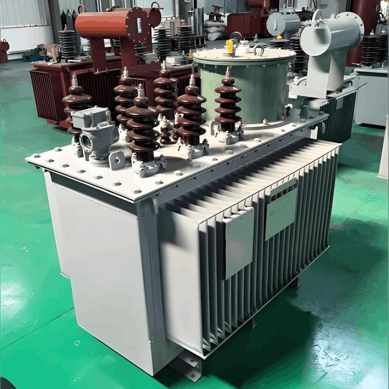
Adjusting the on - load tap - changer of the main transformer :Takes the substation bus voltage as the reference. However, frequent adjustments affect the safe operation of the main transformer and cannot ensure stable line voltage.
Switching shunt capacitors :Reduces voltage drop caused by reactive power when the grid has large inductive loads, but the voltage regulation range is narrow.
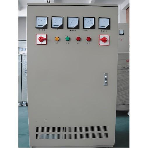
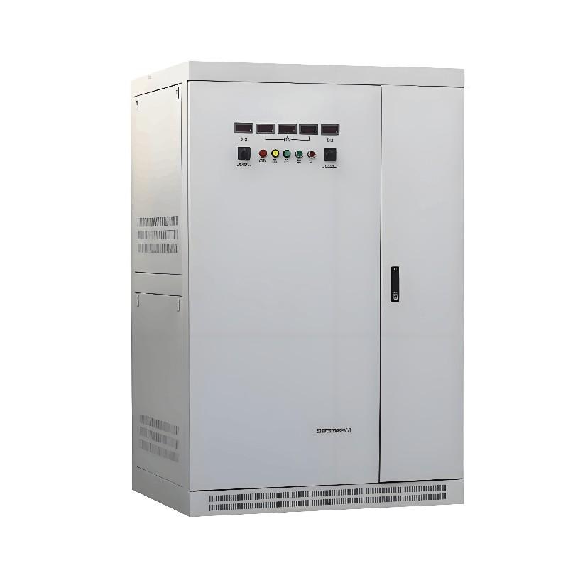
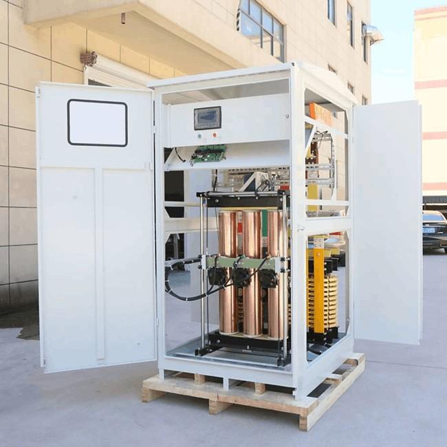
After final discussion, it was decided to adopt a new - type voltage regulation device — the 10 kV feeder voltage regulator (SVR), which effectively improved the voltage quality of the rural power grid.And through the comparison of measures to improve voltage quality in the following table, it can be seen that using feeder voltage regulators is currently the most effective way to enhance the voltage quality of rural 10 kV lines.

Application Example
Taking the 10 kV Tuanjie Line of a certain substation as an example, the installation process of the SVR is as follows:
Identify the critical point where voltage drops exceed acceptable limits.
Select SVR capacity based on the maximum load at the critical point.
Determine voltage regulation range according to the measured voltage drop.
Choose installation location prioritizing accessibility for maintenance.
Calculation Method
Line Parameters:
Length: 20 km
Conductor: LGJ - 50
Resistivity: R₀ = 0.65 Ω/km
Reactance: X₀ = 0.4 Ω/km
Transformer Capacity: S = 2000 kVA
Power Factor: cosφ = 0.8
Rated Voltage: Ue = 10 kV
Step 1: Calculate Line Impedance
Resistance: R = R₀ × L = 0.65 × 20 = 13 Ω
Reactance: X = X₀ × L = 0.4 × 20 = 8 Ω
Active Power: P = S × cosφ = 2000 × 0.8 = 1600 kW
Reactive Power: Q = S × sinφ = 2000 × 0.6 = 1200 kvar
Step 2: Voltage Drop Calculation
ΔU = (PR + QX)/U = (1600×13 + 1200×8)/10 = 3.04 kV
Step 3: SVR Sizing
Step 4: Voltage Regulation Range
Step 5: Loss Reduction Calculation
Post - installation:
Economic Benefits:
This demonstrates that SVRs are the most effective and economical solution for improving rural voltage quality.